VERY nice engage/disengage method! I think you've got yourself a winner.
Thanks, still plenty to do. Always a work in progress.
Nice- be sure to fit a cover to keep chips out
Did you do the anodizing yourself?
Mark
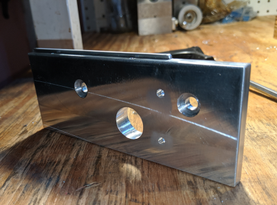
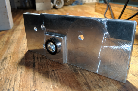
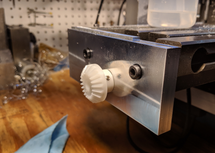
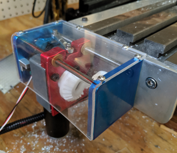
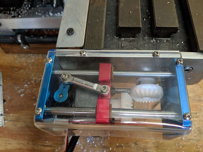
Photos below with her shiny new acrylic cover in place. I ordered a sheet of 2mm aluminum for the cover, but while she's in shakedown mode I wanted to see what was going on under the hood. Turned out kinda neat, so I may keep it for a while. I'm sure after a while it will get scratched and dulled with swarf splooge and I'll want to replace it with the aluminum.
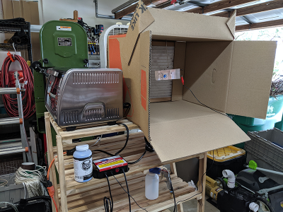
The parts are powder coated not anodized. Another new skill that I've yet to master. Photo below of my high tech powder coating booth.

A/C filter in the back and box fan minimize powder dispersion.
very neat! Do you have to turn the speed to zero to reverse? The motor seemed to be moving back and forth a bit on the guides on the return, but not the other way. Any idea why? Maybe a rigid servo arm might help keep the bevel gears meshed fully in reverse.
Very impressed with both the mechanics and the electronics.
Thanks Matt. No, the reverse switch and motor will happily change direction at any speed. If I switch off the power switch while the servo is in the engaged position, it stays engaged, so that's another, less abrupt, option for changing direction (power off - change direction - power on).
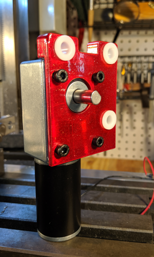
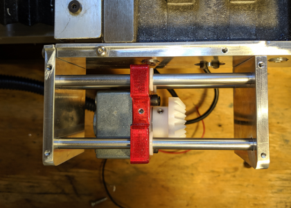
As for the motor wobble, there are a couple of issues that I'm looking at. First, the nylon gears are not super precision, not terrible, but not what I was expecting. Part of that may be my lead screw adapter. It slips over the lead screw with a rolled pin which fits into the slot of the lead screw. Then it's turned down to 8mm with two flats to fit the gear. Since I don't have a lathe yet I made it using round stock and turning it down using a boring bar on the external face. I'm sure a lathe turned adapter would be more precise.
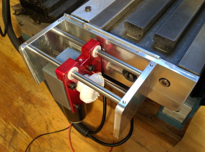
See the photos for the new servo arm and linkage. The video was the proof of concept test.
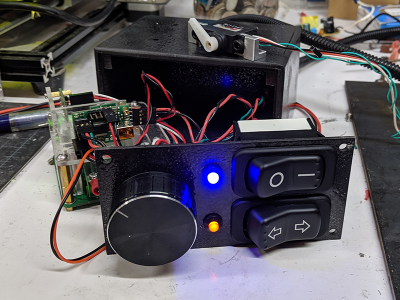
I'm thinking I need to change a couple of things. Any time that the PF power switch is on the servo constantly twitches. After a couple of minutes powered on, even though I'm not using the PF, it gets hot enough that it can't engage/disengage. (Or maybe it's just tired from twitching.) Switch the power off for a few minutes and she goes fine again.
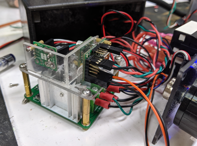
I used a PWM controller for the motor, so that's the first thing I'm going to try to change. I know that they are more efficient than just using a potentiometer, but the voltage sensor never sees a constant voltage from it and will occasionally engage/disengage the servo at random times. Electronics is definitely not my strong suit, but if I understand the way a PWM works, I believe the voltage sensor, being digital, is occasionally seeing the 'gaps' in the wave instead of a steady voltage that the DC motor sees. I tapped this down considerably by adding a 750ms delay to the script of the servo controller, but I think that is the reason for the constant twitch.
I also may just need a more powerful servo. This one is considered a micro-servo with a torque about 1/25th of what a RC car servo can deliver. Of course those servos are bigger so I'll have to machine a new rear plate if I go that route. In that instance I'd probably mount the servo 90° clockwise, putting the linkage lower and parallel to the end plate on the ways, which would let me attach the linkage to the motor mount directly between the inboard rails and closer to the axis of the gears. The current location is causing some binding just because it's pulling/pushing from the very top of the mount. I'm sure that the ideal pressure point would be dead center of the three rails (on the back of the motor gearbox), but that will require considerably more real estate on the back side.
The adventure continues. Again comments and suggestions are welcome. I'm just making this up as I stumble along.