Logan Model 1875 Info

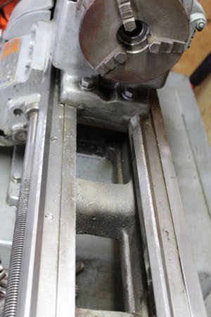
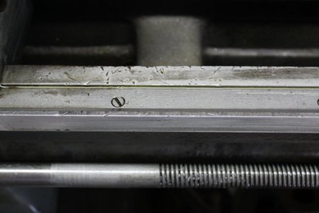
HiCap239, MBfrontier was not talking about a twisted bed, he was describing how to check for a worn bed. With bed wear, which is usually mostly near the chuck, the ways become worn downwards, making the distance from the top of the ways to the carriage clamping surface below the ways less. If you tighten the carriage while it is near the chuck and then loosen it just enough that it moves with slight resistance, and then move the carriage to the right where there is typically less wear, you can see if the carriage gets harder to move as it goes to the right, indicating wear near the chuck. It is a quick and dirty test, and does not quantify the extent of the wear very well, but at least it gives you an idea of what is going on. Looking at the ways visually will not really show much beyond extreme wear and physical damage, (dings, etc.)

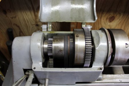
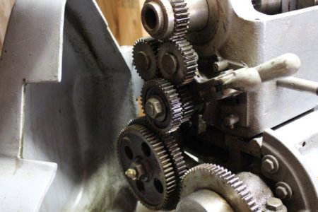
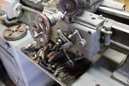
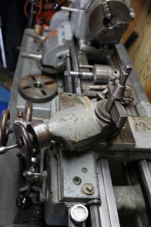
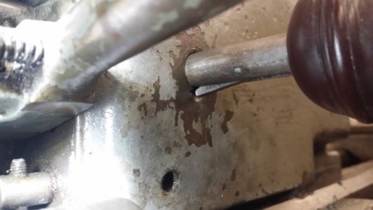
Thanks for the info, I was wondering about that. I did just what was stated above. I just did not know what It was called. I also stuck a straight bar against the front part of the prism way by the chuck out 10 inches and put a flashlight angled down angled down and against the bar and inner flat way. You can see light which gives a somewhat more accurate means of measure. When I did the twisted bed test it did indeed get harder to turn as the carriage approached the tail stock area. However it did not get so tight that I could not turn it. I snugged it up until it was not to easy to crank in front of the chuck. I ran it back and forth several times, next I ran it up within 3 inches of the chuck and grabbed the back of the carriage and grabbed the bottom of the Apron and tried to life it. There had to be some play, but I really could not detect it. I did this in various other places then went back to the front section and still could not tell any discernible difference. Unfortunately there is no steady rest, or a 4 jaw chuck for that matter not much in the way of tooling. His money is in measuring equipment. Lots of Starrett stuff, along with Brown & Sharp. Gears checked out A ok all the way around. He had the thing dripping with oil when I got there. He had it for 9 years and bought it from an old timer he knew that was familiar with lathes. I also checked the change gear box gear sets running and not. All were good to go. One issue I need information on is the machine would drop out of gear when running sometimes. The (Excuse my ignorance on the proper name of this) lever on the left of the gearhead assembly that engages the gears with the black knob (see pictures) up above the quick gear change box seems to have a lot of slop in it. I felt underneath it and it feels like there is a keyway slot of sorts. I have no idea how "tight" this should be but it seems to have what I would consider a lot of side to side play in it. I can see it rides on top of something possibly a shaft with a gear on it inside of the upper gear assembly. When it drops out of gear the seller shut down the unit then pulled while wiggling the bar/knob assembly back out and it would lift the gear back up into place. He said it must need adjusting and he did not know anything about it so he did not want to mess with it. Any info would greatly be appreciated. He was honest and let me take my time and all the pictures I wanted of it and run it as long as I wanted. Here re some pictures with my good camera. I told him there was no way I was going to trade him what I had for that even with the tooling. I did offer up a lesser trade that I felt would be fair for both of us and that he could keep the measuring instruments. He said he was good with that, but he wanted to wait since he had spoken with a gentleman from the other coast and promised he could come and look at the lathe this Wednesday. He said he had a better trade, so the deal was left for him to consider until the other guy looks at it. Looks like I will not know anything until Wednesday or later on whether or not I will get the lathe. Let me know if anyone sees anything in the pictures that I have not have described and may have missed. I also pushed and pulled the chuck and there was no movement back and forth so it was good also. Thanks guys and enjoy the pictures.
1875_1.JPG

1875_2.JPG

1875_3.JPG

1875_4.JPG

1875_5.JPG

1875_6.JPG
 
It sounds like the little catch on the bottom of the back gear rod is broken. That would be the knob above the qc box. I was going to comment about it in the original pic. I noticed it was pulled out, which should mean that the back gears are engaged. Sometimes they get adjusted incorrectly and they work backwards. To engage back gears you unlock the spindle from the bull gear and then pull the knob out until the spring loaded lever on the bottom of the rod clears the front of the headstock casting and locks it in the extended position. To unlock it you lift up on the little lever and push the knob back against the headstock casting. The you push the pin back into the bull gear and your back in your high speeds
 
It sounds like the little catch on the bottom of the back gear rod is broken. That would be the knob above the qc box. I was going to comment about it in the original pic. I noticed it was pulled out, which should mean that the back gears are engaged. Sometimes they get adjusted incorrectly and they work backwards. To engage back gears you unlock the spindle from the bull gear and then pull the knob out until the spring loaded lever on the bottom of the rod clears the front of the headstock casting and locks it in the extended position. To unlock it you lift up on the little lever and push the knob back against the headstock casting. The you push the pin back into the bull gear and your back in your high speeds

We did check the back gearing he marked the spindle where the pin goes through from the bull ear to make the process easier. Where is the little catch located at on the back gear rod? on the outside or the inside? Also is it an easy fix in which something can be fabricated or do I have to purchase one? Also is there supposed to be a lot of side to side slop in the back gear rod? I need to find a parts schematic so I can see exactly what is going on to really know since I have never seen one before. Thanks for the info, I have a direction to go now.
 
If the only issue is the back gear rod, you're in good shape. It's real common to find the catch broken or missing on those machines. The side to side slop I'm not familiar with. I couldn't imagine the case being worn....or the rod for that matter. You can make a new catch for it with a saw and a grinder. It's a lot easier if you have one for a pattern. I can take a picture of mine tomorrow just to give you a better idea what we're talking about. There's a tiny spring under the catch lever that might still be stuck in there. If not you can find one at a hardware store. Do you remember if it was in back gear when the knob was pulled out?
 
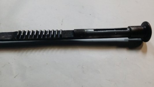
The latch on the back gear rod is underneath the rod in a slot: it's a small, spring loaded metal part that pivots on a pin. If it's broken or missing, Logan can supply the parts.
I bought them for mine, and while I don't remember what I payed, they aren't expensive.
That's easy to fix.
 
Here's a pic. The first one is on my 1875. The second one is a spare that has the latch missing. 20170304_195716.jpg 20170304_200058.jpg
 
As others have stated, the shaft with the black knob is the back gear shifter. To shift the lathe into "low range" the pin on the bull gear is pulled out and the back gear shifter rod is pulled out. This is mainly used in single point threading. It doesn't matter that the shifter seems a little loose as long as it keeps the back gear engaged.

The key on the bottom of the back gear rod is spring loaded to pop out and lock the shifter in place against the face of the head stock when the rod is pulled out in the fully engaged position. My Logan 1957 lathe had a worn key causing the shifter rod to slip back into the hole and disengage. In addition, there was a small ramp worn in the bottom of the shifter hole in the headstock casting compounding the likelihood of disengagement. Luckily, I discovered this condition while refurbishing the headstock. The solution was to cut a small piece of steel plate using the worn key as a template but eliminate the worn ramp on the end of the key. In my case, that was sufficient to eliminate the issue. In any case, it shouldn't be a major issue and the fix should only cost a little of your fabrication time.

Since you will have to remove the shifter rod from the lathe to work on the key you should take a look at this document on the Logan Lathe Website which will instruct you how to properly install the shifter after your work is complete. Here is the link:
http://lathe.com/ll-group-archive/logan_lathe_back_gears.html

After looking closer at your pictures I realized the lathe looks like my Logan 1957 which I like a lot. I took a look at my manual and saw that the manual for the 1957 model includes the model 1875. So, welcome to the family I think? Did you buy it?
 
Last edited:
As others have stated, the shaft with the black knob is the back gear shifter. To shift the lathe into "low range" the pin on the bull gear is pulled out and the back gear shifter rod is pulled out. This is mainly used in single point threading. It doesn't matter that the shifter seems a little loose as long as it keeps the back gear engaged.

The key on the bottom of the back gear rod is spring loaded to pop out and lock the shifter in place against the face of the head stock when the rod is pulled out in the fully engaged position. My Logan 1957 lathe had a worn key causing the shifter rod to slip back into the hole and disengage. In addition, there was a small ramp worn in the bottom of the shifter hole in the headstock casting compounding the likelihood of disengagement. Luckily, I discovered this condition while refurbishing the headstock. The solution was to cut a small piece of steel plate using the worn key as a template but eliminate the worn ramp on the end of the key. In my case, that was sufficient to eliminate the issue. In any case, it shouldn't be a major issue and the fix should only cost a little of your fabrication time.

Since you will have to remove the shifter rod from the lathe to work on the key you should take a look at this document on the Logan Lathe Website which will instruct you how to properly install the shifter after your work is complete. Here is the link:
http://lathe.com/ll-group-archive/logan_lathe_back_gears.html

After looking closer at your pictures I realized the lathe looks like my Logan 1957 which I like a lot. I took a look at my manual and saw that the manual for the 1957 model includes the model 1875. So, welcome to the family I think? Did you buy it?

Thanks a million for the info on the rod, guys. When I felt underneath of it I did not feel the spring loaded pop out or anything but the channel for that matter. Also thanks for the pictures and link to the schematics of that rod assembly. So the deal on the lathe is pending right now. He has another guy that wants it and may have a better trade. That gentleman is supposed to come over from the other coast on Wednesday. From what the seller of the lathe said the guy wants to trade two very expensive items for the lathe, I am skeptical that the guy will trade or even show up for that matter. So at this point in time I am just waiting. There was one other small thing or maybe not. When I turned the tool post cross slide wheel I noticed it had a small wobble. Like it may have gotten bent, not sure maybe it is an adjustment. It was smooth, but if you pulled on the cross slide it would move a small amount back, I am thinking it can just be adjusted out. If I have to rebuild it I will as that is not too much of a problem. I really do not to think to much about it or make plans. Usually when I start doing that the deal falls through. Just my luck sometimes. So I will have my fingers crossed in hopes to get this machine. I see a rebuild down the road if I do.
 
I have an update on the Logan 1875 Lathe trade deal. It looks like the other gentleman that was going to meet with the Logan lathe owner was a no show today so the lathe deal with me is going to go through. I will be picking up the Logan 1875 this Saturday or Sunday.
Here's a pic. The first one is on my 1875. The second one is a spare that has the latch missing. View attachment 227896 View attachment 227897

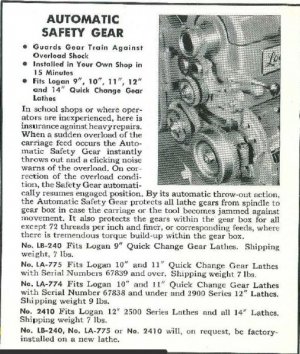
Thanks for the pictures. Logan 1875 update, looks like I will be doing the trade deal this weekend probably Sunday. I am looking forward to getting this thing up and running. I will looking for some sort of dimensions for that missing shifter rack pin as it appears that the one on this lathe is missing. It should be easy to fab one up, it is just getting the size information to make it up with. Does anyone know where I can get some dimensions for one of these? I will post pictures later next week when I get it settled in. Thanks again guys!
 
A 6" vise is overkill for a RF45 style mill. A 4" is more appropiate for that size mill & IMO 5" max. I have a 5" GMT vise on my PM45 & it's slightly too big. Not enough Y axis travel to make use of the 5" full capacity. Better to save your money rather than getting something too big & most importantly the weight. I take my vise of the table quite often, a 6" is still light enough for me to be carried by hand but I'm glad I have a 5". I also have a 4" vise as well. I prefer the 5" though.

But those GMT 6" Premium vises are pretty nice. I'd love to have one but don't need one on my current mill. But if you plan on upgrading to a full size knee mill in the future than the 6" will be perfect.


Here's what the 5" looks like on my mill.
Img_1921.jpg


I couldn't even complete this cut without my bellows & DRO scale getting in the way. Not enough Y travel & the 5" vise is not even maxed out.
Img_7597_zpscb8b5dd7.jpg


Here's what a 6" vise looks like on another PM45 (gt40's)
View attachment 253544

Capture.JPG
 
Last edited:
Back
Top