Logan Model 200 Servo Threading

Excellent! I am glad you is working out for you with the added bonus of FUN. You are doing something most of us would not even consider. If you could add pictures of your work we'd greatly appreciate it. Photos really add a lot to the story, particularly for those of us that are more than out of our element. Keep up the good work.

Thanks for the encouragement. When I have something picture-worthy I intend to post it.

I think I've worked out how to make the change-over from gears a clean swap. I'm waiting for a few more parts, then I'll be making brackets for the stepper motor and rotary encoder to mount them on the banjo in place of the change gears. Timing pulleys will replace the screw and spur gears. Belt tensioning will be accomplished with the banjo. That will keep everything looking neat, fit under the cover, and be worth taking pictures of. It will also make it easy to change everything back.

I'm going to start with a 5:1 reduction between the stepper and the lead screw. With the stepper spinning 1000rpm (half max) the carriage will move the full length of the bed in under a minute, which seems fast enough to me.

I picked up a 2.8" color display with a resistive touch screen that I think, along with a knob, will make a good user interface. After I got the display I read something that implied that it used up all the Arduino's pins, but after looking at the schematic I don't see a problem.

Initially I plan to make it function purely as a continuously-variable gearbox. I suppose it will have to have a fast jog function so that the half nuts can stay engaged for metric threading. I like the idea of prompts to remind you where to engage the threading dial for a given pitch. What else do you think would be useful?
 
If you don't have pictures it didn't happen, right? Baby steps.

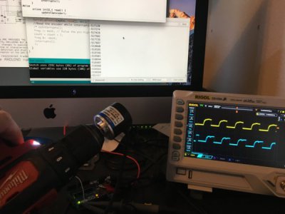
IMG_1600.JPG

The encoder is plugged directly into the Arduino and running from 5V. You can see that the Arduino internal pullups are pretty weak.

I highly recommend these little Rigol scopes, by the way. I see that they're going for $350 on Amazon Prime. I paid $399 for mine a couple of years ago. Great little scope.
 
I thought I ought to post a progress report to pique the interest of the vanishingly small number of people who might actually be interested.

The Arduino Mega is going to get it done, I think. I have the prototype interrupt-driven low-level code working well, covering inch feed rates from 0.0005" to 0.250", from 0.01mm to 4.5mm, and the pitch of every tap available from McMaster-Carr.

Then I thought "why stop there?" So I'm adding diametral pitches from 112 to 12, and module pitches from 0.2 to 7. It's no harder than doing metric feeds, so why not? I got the tables from pictures of a Victor lathe that I looked at on eBay and thought it would just be cool to do.

I'm still waiting for slow boats from China, but should have all the pieces within the next week. I do have the leadscrew timing pulley machined, but have other pulleys to adapt and brackets to make.

I'm hoping to start work on the GUI this week. Pictures soon, I hope.

All the best, folks!
 
Plenty of interest here.

Having a simple setup that cleanly attaches at the banjo is a really good idea. There are many, many change gear Logan's out there that would benefit tremendously from this setup. My problem is that I have no electronic experience, wouldn't know where to start, and really can't add much to the conversation.

Once you show a setup that can cut a variety of thread pitches with the push of a button, you'll have plenty of requests for hardware lists and code. Keep up the good work.
 
I'm still making steady progress, if anyone is interested.

I'm driving a stepper motor and it's looking really good. I couldn't get the noise immunity that I wanted on the ATmega2560 with full quadrature decoding. I just couldn't make it behave with the interrupt latency and the slow, sometimes noisy rising edges, so I changed the logic to interrupt on falling edges of one phase and simply read the state of the other. I gave up resolution, but gained very quiet and stable tracking of the spindle right down to a dead stop. I started with a 200p/r rotary encoder because 800 counts per spindle revolution just scaled really nicely to the stepper controller, and now I'm waiting for an 800p/r encoder to get that back with the new decoding scheme. I may try full decoding again when I get the voltage-output 200p/r encoder that I also have headed my way.

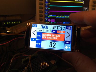
There are practical limitations on how fast you can feed for a given spindle RPM, just like with gears, so it will tell you what that maximum RPM is, warn you if you're trying to go too fast, and simply refuse to go if you're exceeding the limit.

I have an encoder knob hooked up and working well (with a bit of debouncing) for changing parameters in the user interface. And I have a "smart" Nextion 3.2" display connected to the Mega's third serial port which is going to take some time to figure out. The extra ports are another reason to go with the Arduino Mega. I can be debugging over Port0 while controlling the display over Port2.

I hope it won't take too much longer to get all the pieces working together on the lathe. Stay tuned.
 
Can't wait to see the drive motor mount and the spindle speed pickup.

As to other features, using the display as a spindle tach when you're not driving the screw would sure be nice.

Since you're counting turns, can you create a feature to set/reset an infeed limit to help avoid crashes?

Very interesting project.
 
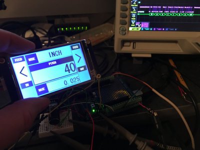
Several iterations later it looks like this. The icon in the lower right is the placeholder for feeding to a shoulder. I still have to write that code. Actually, everything is a placeholder since it's just a mock-up. But I am talking to the display at this point:

IMG_1614.JPG
 
When you say "talking to the display", do you mean the stepper motion and direction? Just wondering what you start with on something like this.

From what I can find on-line, there's graphical interface programs to set up the display, and separate code for the Arduino. There appear to be various "starter kits" for both the display and the control board. Any thoughts on which kits might be a good starting place for a digital dinosaur? I got off the programming train at Fortran and punch cards.
 
Frankly, I think the display has a lot more raw processing power than the Arduino Mega that I'm using for motor control.

At this point I can send commands to it over the serial port. The Mega has four serial ports. Port 0 is used in the Arduino environment as the debugging port, and I have the Nextion set up on Port 2 (because that's what their examples use). All I've done so far is send text to it, but that's most of what I'll be doing anyway. The Nextion itself can handle most of the user interface, and only send the button press events to the Arduino to let it know when something is changing that the Arduino needs to know about. I've already set up a second page to control the display brightness, but the Arduino doesn't need to know that, though I might have the Nextion check the RPM and not switch pages unless the spindle is stopped, for instance.

Nextion provides an editor to set up the display, and I'm gradually figuring it out. The display itself keeps track of when a "button" is pressed and highlights it. For the left and right feeds, for example, I have it sending a button press event and a button release event to the Arduino. That way, holding the button pressed will allow me to traverse the carriage, and feed faster the longer the button is held. All I need for the inch, metric, diametral and module buttons is the press event, though.

On the Arduino side, you have to use the name of the display object that you defined in the Nextion editor to send commands. So if I want to display RPM in the appropriate text box I send "rpm.txt=" followed by the string. There's nothing to stop you changing any number of other attributes. You could conceivably leave nearly everything undefined and configure the entire display by sending commands to it.

Communication in the other direction is different. For instance, when I press the left feed arrow, the Nextion sends 0x65 0x00 0x0E 0x01 0xFF 0xFF 0xFF to the Arduino. The first byte is the "Touch Event", the second byte is the page number, the third byte is the component ID, and the fourth byte indicates a Press, followed by a three-byte terminator. When I release the button it sends almost the same thing, except that the fourth byte becomes 0x00 indicating a Release. So you need to keep track of component names and numeric ID's on the Arduino side to manage two-way communication. Clear as mud, I'm sure.

After you've designed the Nextion display look and behavior, it creates a file that you copy to a MicroSD card and plug into the display. When power is applied it copies the file to its on-board memory and runs it. It can also be done serially, but I haven't tried that.

The display was about $30, and the Arduino Mega about $20. I also got a "shield" for the Arduino with screw terminals and a prototyping area for about $10. Arduino and Nextion provide free downloads for their software. So just buy some stuff and give it a try. My first exposure to a computer was running an IBM 1230 Mark Scoring Reader with a card punch console attached, for a Work-Study job at the University of Northern Colorado back in the early 70's. The grading scheme was "programmed" with rotary switches on the front panel. Once I had to deliver 50,000 punch cards to the real Computing Center for analysis. I was a Music major, and didn't actually get into computers for real until a few years later.
 
Back
Top