After milling the dovetail in the bottom of the new casting, I took some time to lap the bottom using coarse sandpaper on my surface plate (with water as a lubricant).
Next up was to mill the bevels on the gib. I had to decide whether to build a one-time-use fixture to hold the gib, or just use available tooling and figure out some way to hold the gib at the required angle to the tool. I opted for the latter.
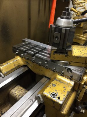
The simplest thing I could think of was to again use dowels and my adjustable parallels (handy little suckers):
View attachment 106122
This isn't the most secure workholding in the world, but I figured it would suffice. At first I only hand tightened the parallels by squeezing the wedges with my fingers, but eventually I wised up and started tapping them tight with a small tack hammer. Also, I eventually learned that (unlike the picture shown) I should ensure that I locate the outermost dowels as close to the front and back edges of the slide as possible (to provide better support at the ends of the gib).
Then I took extremely light passes (0.005" at a time) with pretty slow feed rates (power feed). I was careful to mill in the correct direction (table moving from left to right, with the cutter moving from top to bottom as photographed above) so that the gib was pushed back into the dovetail as the leading edge of the cutter hits the gib.
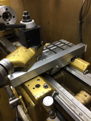
It was probably unnecessary to mention this, because only a
complete idiot would risk throwing a part just to save a little time by milling in both directions and taking too heavy a cut.
View attachment 106123
Ahem.
For what its worth, I'm
very fortunate that I didn't chip my expensive carbide end-mill or (much worse) injure someone (me!) when the part was thrown. Even though I only had the slide lightly clamped, I was still surprised that there was enough force to pull it out of the clamps.
Lesson learned. This was when I got out the hammer to better tighten the wedges and started taking my time with light, light passes. I even slowed the feed a bit more once I started taking wider cuts as the quill was lowered.
Here's what it looked like as I was taking 0.005" at a slow feed rate (just to show how little I was actually taking off each pass).
On the first edge, I didn't mill down to a sharp knife edge. I left a tiny little bevel on the edge to ensure that I had enough material to mill the other side. I figured I'd be knocking the sharp edges off with a file when I was done anyway.
View attachment 106124
For the other edge I just flipped the part and stole the idea from Paula on the South Bend forum to use some 3/32" rod as a spacer to lift the part enough to mill. Then rinse and repeat.
View attachment 106126
Like spelling "banana," the only tricky thing about the second edge was knowing when to stop.
")
I wanted to ensure that the gib was narrow enough not to bind top-to-bottom in the slot, but I didn't want to mill off any more than necessary. This didn't need to be a super accurate measurement, I just didn't want the gib to bind. The solution was pretty simple, just use another piece of the 3/32" rod as a gauge on top:
View attachment 106127
The camera angle is pretty awkward, but in person it was obvious that the gib was higher than the gauge rod (the square wasn't vertical):
View attachment 106128
I just kept milling until the square tipped the other way. Here's a shot from the other side once I was just about done (I think I took off another 0.005" just for good measure). You can clearly see that the squares are touching at top, but there's a gap at the bottom.
View attachment 106129
Finally, here's a shot showing the finished gib in place on the slide (finished except for cutting it to length — I did that off camera):
View attachment 106130
In this final shot of the gib in place, you can see one little detail I forgot to mention. When I cleaned up the casting scale in the slot on the bottom of the raw casting, I was left with a trench quite a bit deeper than the original part. At first I just started milling away on the roughly-formed ways to lower the gap, but eventually I chickened out. Instead of reducing the depth to final dimension, I reasoned it was okay to leave a little more "meat" on the sides. The trench isn't a precision bearing surface anyway, it just needs to provide clearance. Here you can clearly see the little "extra" gap I'm talking about (I don't think it will hurt anything):
View attachment 106131
Next up is to bore and tap the holes for the gib screw, gib pin, and lock screws. I also need to make the lock screws.
Enjoy!
--
Rex