- Joined
- Jun 28, 2021
- Messages
- 142
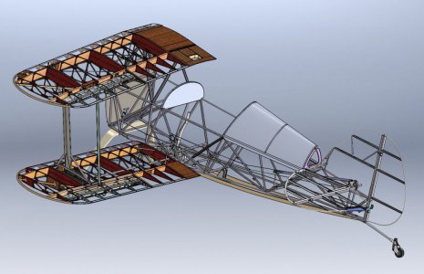
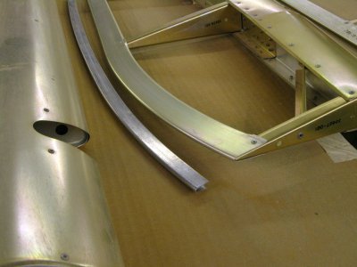
The goal of this project is the create tooling for my Pullmax that can produce a part similar to the Christen Eagle curved aileron trailing edge shown below. Also shown below is my first test part which does not have a tight enough curve for my Pitts S-1 which has a smaller wing tip radius than the Eagle part. The Eagle part was stretch formed and it is beautiful. I'm not sure this can be done in a Pullmax but I thought to give it a try.
The shape formed by the curved trailing edge is a shallow double-ended cone. That was a fun one to try to machine tooling for.
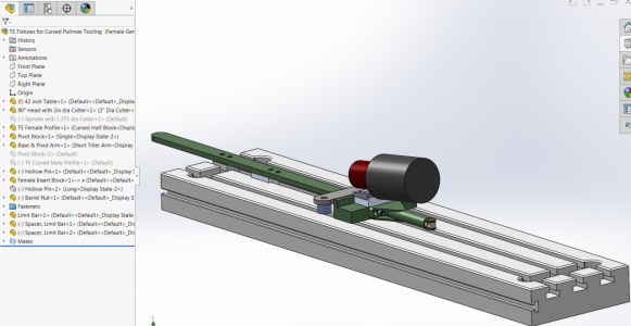
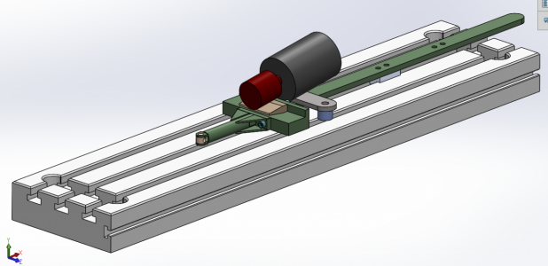
This is the machining fixture modeled in Solidworks. The Bridgeport table is modeled as is the business end of the 90° head (dark gray) and a 2" dia endmill (in red). The part being shown here is the female die half. The arm with the little barrel nut is the end I will move with a long screw to pass the blank under the cutter. BTW, that arm got much longer after doing the first cuts.
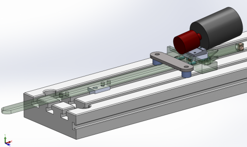
This view shows the pivot block under the pivot arm. It's a T-nut with a C-bored hole for a SHCS and threaded hole for the pivot bolt.
This is the setup for the male (punch). While the female blank sits on an adapter block the male is attached directly to the fixture base block. And a slightly different pivot radius is used for the male part mainly because of where the blanks end up with and without the adapter block being used. The male blank is simply flipped over to machine the other side.
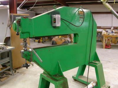
And this is my Pullmax P3 with the trailing edge tooling installed and a test part being formed. The Pullmax is like a big rigid C-clamp but having one side of the clamp reciprocating up and down a small mount (less than 1/8") and it does this at pretty high speed (~400 strokes/minute).
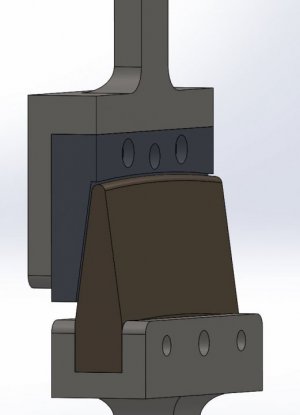
This is a partially sectioned view of the Pulmax tooling.
This is the way I did the original PVC female part. The traverse was done with a hand drill. For the steel parts I did a manual feed.
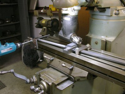
The plastic part behaved pretty well with this setup, the steel part not so much. I had to add to the force being applied to hold the base block down to the table.
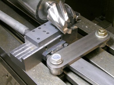
High-tech feed mechanism.
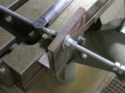
Action shot.
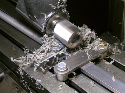
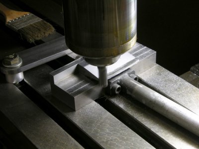
Things are close together by necessity. Now the fun begins with the steel part. Note the added hold-down bar and fancy hand-feed design.
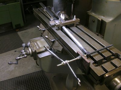
Close to the final pass. The surface cleaned up more than well enough for this parts' intended use. The other side has yet to be machined.
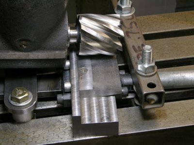
Final steps were to machine the arc on the end and apply a radius.
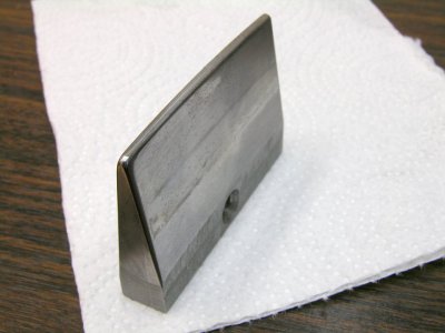
The finished gen1 punch.
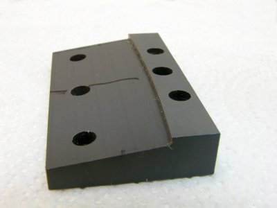
And the PVC die half fresh from the milling machine.
Not sure how I would have done this with a pencil and paper for design tools............Bill
The shape formed by the curved trailing edge is a shallow double-ended cone. That was a fun one to try to machine tooling for.

This is the machining fixture modeled in Solidworks. The Bridgeport table is modeled as is the business end of the 90° head (dark gray) and a 2" dia endmill (in red). The part being shown here is the female die half. The arm with the little barrel nut is the end I will move with a long screw to pass the blank under the cutter. BTW, that arm got much longer after doing the first cuts.

This view shows the pivot block under the pivot arm. It's a T-nut with a C-bored hole for a SHCS and threaded hole for the pivot bolt.

This is the setup for the male (punch). While the female blank sits on an adapter block the male is attached directly to the fixture base block. And a slightly different pivot radius is used for the male part mainly because of where the blanks end up with and without the adapter block being used. The male blank is simply flipped over to machine the other side.

And this is my Pullmax P3 with the trailing edge tooling installed and a test part being formed. The Pullmax is like a big rigid C-clamp but having one side of the clamp reciprocating up and down a small mount (less than 1/8") and it does this at pretty high speed (~400 strokes/minute).

This is a partially sectioned view of the Pulmax tooling.

This is the way I did the original PVC female part. The traverse was done with a hand drill. For the steel parts I did a manual feed.

The plastic part behaved pretty well with this setup, the steel part not so much. I had to add to the force being applied to hold the base block down to the table.

High-tech feed mechanism.

Action shot.

Things are close together by necessity. Now the fun begins with the steel part. Note the added hold-down bar and fancy hand-feed design.

Close to the final pass. The surface cleaned up more than well enough for this parts' intended use. The other side has yet to be machined.

Final steps were to machine the arc on the end and apply a radius.

The finished gen1 punch.

And the PVC die half fresh from the milling machine.

Not sure how I would have done this with a pencil and paper for design tools............Bill
Last edited:


