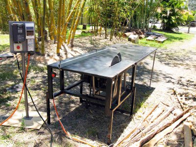
Made a 14" table saw
14" Table saw build.
Hi Guys, I needed a table saw so that I could slice and dice up some timber from the slabs I milled from 3 logs I had, this would enable the timber to dry out faster and give me an idea
of how much useable timber I ended up with. Had a 4HP 3 phase motor lying around in the shed and an old aquarium stand as well, so thought it was about time I did something with
them.
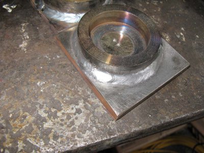
1. Made 2 bearing holders to fit 30mm ID bearings. Bored out some holes in some 80mm round bar, cut them off and welded them to some 10mm plate.
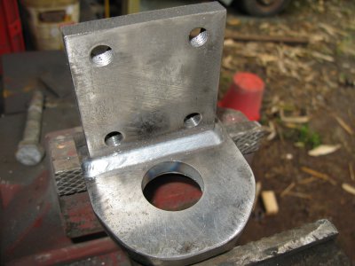
2. Welded a side plate at 90 degrees, these get bolted down to the frame and hold everything together.
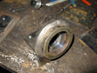
3. Other side of the bearing holder.
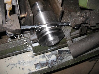
4. Roughly turned a double pulley out of a larger round bar and turned down one end as that will be where the M10 grub screw locks down the shaft key. After it was cut, it was
drilled to size and then the pulley was welded to a piece of 40mm stainless rod. The lot was then machined to make it all true and remove any distortion made by the welding.
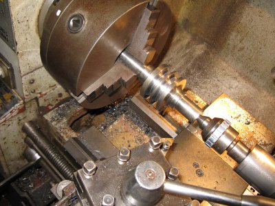
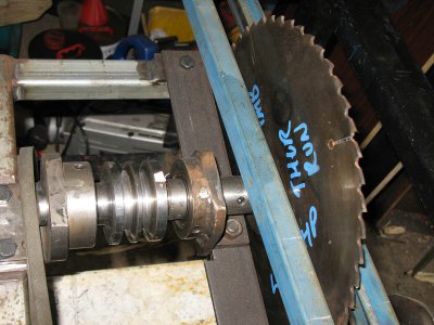
5. I put a thread on the end of the shaft to accept a threaded blade hub, but later on I had to remove that thread and made a new hub (Pic 8.) with straight through hole and a
larger flange. Having the thread on the end gave the blade a very slight wobble which at full revs would look normal till I started to cut some timber and then the blade would
oscillate dangerously, couldn't work out why till I connected up the VSD to it instead of directly to the power and dropped the speed down to 500 RPM and then I could just
barely see the wobble, at full revs the centrifugal force made it all look straight and hid the wobble until I started cutting. Probably from too much tolerance between the
male shaft thread and the female hub thread.
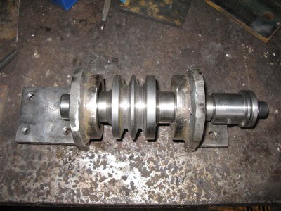
6. Shaft assembled (showing the old hub)
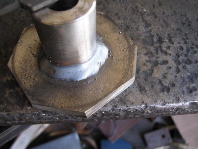
7. Making the new hub. Drilled some steel rod, welded it to some plate, cut the corners off and attached it to the shaft, put the whole lot in the lathe, used a steady rest on
the bearing and machined the lot true. there is a M14 x 1.5mm bolt which clamps the blade to the shaft and hub plus a M10 grub screw, no more wobbles.
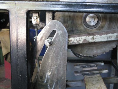
8. Plasma cut out a slot in some 5mm plate to fit a M14 x 1.5mm bolt which clamps the frame to the right blade depth.
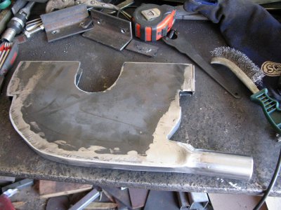
9. Plasma cut out some 3mm plate to make the lower blade cover/dust collector, added some 3mm x 25mm flat bar for the sides and added a piece of 40m tube for the extractor hose
to clamp to.
Originally this was going to be a 12" saw, so I made the frame to suit but with the drama I had with the blade wobbling I ended up getting an old 14" blade to see if it was a
faulty blade(which it wasn't), so I figured I might as well make it to accept 12" and 14" blades, which also meant I had to take out some bits from the sides to make it fit. The
larger blades come close but there is still enough clearance (just).
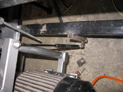
10.Added a strut for lift assistance when raising or lowering the frame, with the 4hp motor added the frame weighs approx. 60Kg so awkward to lift even when the other end is
pivoted, the strut makes the lifting job easy.
- - - Updated - - -
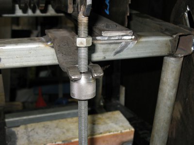
11. Added a "micro adjustment" setup, 13mm threaded rod welded to a pivoting top, a turned, threaded and knurled round bit of rod for accurate height ajustment with a locking
nut to keep the setting, the knurled adjustment is grabbed by a piece of slotted flat bar which had the flats twisted in and ground out to fit the top of it.
12. Welded some 1" SHS tube on either side of the blade to the frame body to support the top plate which stops the 3mm top plate from sagging/bending near the blade.
13. Oiled both the underneath of the top plate and the top of the frame body and then applied liberal amounts of silicon adhesive between the two to make a seal so that the top
plate doesn't vibrate in operation. As the frame was an old aquarium stand which I turned sideways and added some legs, the fit between the plate and the frame wasn't perfect
and doing this way would allow me to remove the top plate if neccessary at a later stage, otherwise the silicon would have glued it down forever, there are 4 (1/4") bolts on
the sides holding the top down as well.
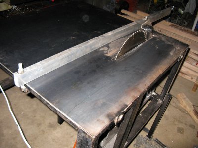
Made a fence out of some 50mm x 25mm x 2mm Aluminium RHS with some bolts welded to some angle underneath and going through the fence. As the bolts get tightened the angle grabs
the underneath frame and locks it in place.
I have also made a 91cm x 230cm extension table for it for when I cut long pieces of timber but I don't have pics of it just yet.
Still to do/make is to cut down the riving blade, make a sliding fence for the saw which will be able to do angles, make a router holder and fence, but I will post those pics
up at a later stage after completion.
Cheers
Ed.


