I've been wanting to make this angle setting gage for my 5" milling machine vise since I first saw it in the Summer 2007 edition of Digital Machinist Magazine. Did I mention I'm a procrastinator. Lol
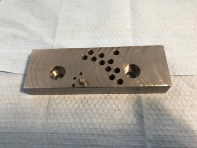
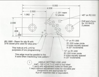
The hole with the dowel pin in it and the eleven similar sized holes are drilled and reamed to .250". The location of these holes in relation to the "pivot" pin hole allows for angles of zero through 90 degrees in ten degree increments. The inner five holes are on a 1.200" radius from the pivot pin hole and the outer holes are on a 1.500" radius. The upper right pin hole is for a 45 degree angle and is on a 2.000" radius. The three smaller holes next to the pivot pin are for a .125" stop pin.
The author claims the maximum error that can be expected is about .05 degrees, or less, but doesn't say what the hole placement tolerance range is.

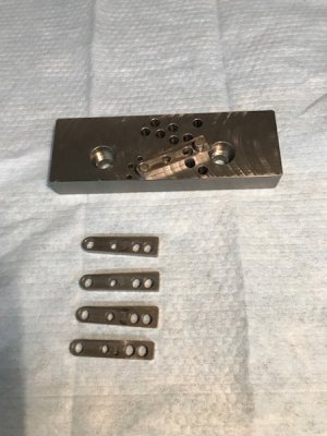
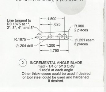
In order to set angles in 1 degree increments a set of five blades was made. The set consists of a 1 degree blade, a two degree blade, a three degree blade, a four degree blade and a five degree blade. The picture below shows the four degree blade installed in the 20 degree pin hole thus resulting in a 24 degree angle. Flipping the blade end-for-end results in a 16 degree angle. If there is a need for a special angle that is between a single degree setting a blade can be made for that setting.

Thanks for looking.
The hole with the dowel pin in it and the eleven similar sized holes are drilled and reamed to .250". The location of these holes in relation to the "pivot" pin hole allows for angles of zero through 90 degrees in ten degree increments. The inner five holes are on a 1.200" radius from the pivot pin hole and the outer holes are on a 1.500" radius. The upper right pin hole is for a 45 degree angle and is on a 2.000" radius. The three smaller holes next to the pivot pin are for a .125" stop pin.
The author claims the maximum error that can be expected is about .05 degrees, or less, but doesn't say what the hole placement tolerance range is.

In order to set angles in 1 degree increments a set of five blades was made. The set consists of a 1 degree blade, a two degree blade, a three degree blade, a four degree blade and a five degree blade. The picture below shows the four degree blade installed in the 20 degree pin hole thus resulting in a 24 degree angle. Flipping the blade end-for-end results in a 16 degree angle. If there is a need for a special angle that is between a single degree setting a blade can be made for that setting.

Thanks for looking.


