Made Atlas 6" Gibs

Andrew R Stewart

H-M Supporter - Diamond Member
H-M Lifetime Diamond Member
Joined
Jan 28, 2019
Messages
62
So after 40 years I finally got around to replacing my Atlas 6" Mk2's gibs. Of course they were the plastic ones and had cracked at the adjusting screw pockets recently when the carriage slide pried off it's ways under cutting forces (I was trying a QC tool post for the first time). I read up here and elsewhere and decided the first thing to do was to replace the gibs with a metal set and see if that improved my opinion of this lathe (which has always been a loosy goosy). I recently posted here in the For Sale sub forum my looking to buy some and wa5cab replied that he might have some soon. As is my nature I wanted them now so made a set from steel flat stock I had on hand and used my mill in a very cold garage. Got to use the mill's new DRO and make a few mistakes, had to start one over. On the test fit to the female ways found one gib rode high so back to the mill for a trim. Tomorrow I'll finish off the clean up of the rest and reassemble then report back. AndyIMG_2398.JPG
 
Actually, at least on the 12", the plastic ones have no pockets as they come. The reason that after years of use they look like they did is that the plastic, being soft, lets the gib screws sink into the plastic farther and farther. And or course, in use that slight softness allows the compound and cross slide to move slightly in reaction to the cutting forces. One thing that this will definitely do is to increase the number of spring passes that you have to make before change in actual diameter equals the dialed in movement. For a long time, I used to wonder why if I dialed in 0.010", the diameter of the part only decreased by 0.017 or 0.018 unless I made several more passes without changing anything.

I'm having a hard time with your photo deciding but it looks like the top of the steel on is squared off. Top and bottom should be at 30 deg. to front and rear.

If anyone else wants to make their own instead of buying them, the cleaned up factory drawings are in Downloads.
 
I should have taken a shot of the milling steps but once you get going it's hard to refocus sometimes:) I'll take a few as I reassemble things. The gibs long edge faces are at 30*/60* WRT the flat faces, ends are slightly chamfered. Interesting tidbit about the plastic ones not having pockets when new. Now I wonder if my made ones will be an issue.

I still want to purchase a properly made set. Much of what I do with my tooling is for my needs and just fun to do and learn a few things along the way. Andy
 
Hi Andy- I made a brass gib for my Mk2 compound and it makes a very smooth sliding gib. I found that 3/8" x 1/8" stock works perfect, and by using a thin spacer piece in the vise under the stock you can cut one side then flip and cut the other side (provided your mill head can nod-looks like yours can)
Mark
 
Andrew, as I mentioned earlier, the OEM drawings are in Downloads.
 
I've reassembled the lathe slides and did a too quick test facing. Interesting results.
The reassembly took far longer then I thought, about half that time was spent on the carriage on bed. Redid steps a few times to get the half nuts and the carriage feed gear together. Thankfully I have small fingers and, it seems, patience (as I was also helping a coworker learn to braze). Next up was the carriage cross slide and the first gib I made. Then the tool holder one. These two went as planned but the gib adjustment took a long time for a, currently, AGAP state. I was running out of time so only was able to do a facing on a steel shaft to make sure all worked, which it did.
The steel gibs definitely fit tighter, with less mushy a feel, but now show how poorly the ways are formed (if I have it right). As each slide is moved through it's travel points of tighter and looser movement happens. Could be that a gib screw is too tight and the friction changes as the slide goes through it's range. I suspect that the ways are not as well made as could be. There's rough tooling marks from the cutter in places, no grinding that's obvious, and the wear on the contact surfaces is not evenly distributed along the dovetails/ways. This machine might benefit from a more anal rebuild with scraping or some effort to better finish the sliding surfaces. It seems that the steel gibs have more friction then the plastic and they are rather sensitive to minute adjustment screw changes, very sensitive. I wonder if a better metal, for the gibs, with less friction would help. I ended up with the carriage cross slide and the tool post slide set a bit tight for now. The slop/backlash/rock has been reduced a bunch.
The test facing went well enough. My tool tip wasn't great yet there was no chatter or womp as the tool tip got to the center of the shaft's face. So far so good.
I think I will consider trying brass soon but suspect the low tolerances on sliding surface finish and parallelness of dovetails will stay as a problem now that the gibs don't compensate to the same degree as before.
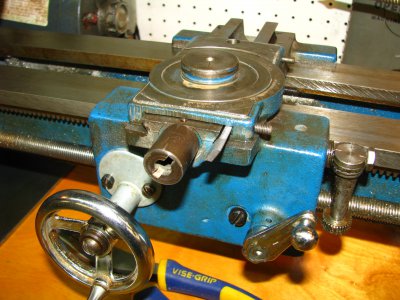
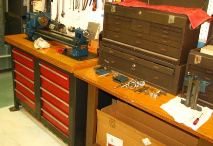
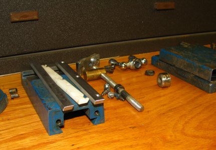
Photos attached are a close up of the first gib being installed, the obligatory parts spread out one and the two gibs with a plastic one better showing the shapes.
I'll continue this playing and update as I find new stuff out (which will be old hat for many here).

wa5cab- Thanks for the dimensional down load point out. I'm much more of a file to fit guy then a numbers are my path one. I will check the plans out and look forward to a better set of gibs in the futuire, Andy
 

Attachments

  • IMG_2407.JPG
    IMG_2407.JPG
    1,013 KB · Views: 29
  • IMG_2405 (2).JPG
    IMG_2405 (2).JPG
    572.8 KB · Views: 31
  • IMG_2406 (2).JPG
    IMG_2406 (2).JPG
    437.8 KB · Views: 28
OK. Glad to hear that they work. But you are literally the first person on several different lists who has pointed out examples of such poor workmanship on an Atlas lathe. There is no doubt that abandoning the 618 for the 3950 and then the 10100 was driven by cost. And especially on the later 10100's there were other obvious cost cutting measures. The plastic gibs is another example. But I have never seen anything as bad as the inner surface of the rear way to the right of the carriage in one of your photos. That is terrible.
 
The other 6" Atlas/Craftsman lathes I've seen (only a few) were all the earlier designs and when I first saw this 10100 I was not impressed. Yet in my youthful want I bought it anyway. The other ones all had very smooth slides/dovetails and a much more solid feel overall.

The carriage's sliding surfaces, that contact the bed's ways, have rather uneven wear and one side has a roughly 3/4" length of no contact what so ever. One can run a finger along the contact surface and feel the step as the no contact area is felt. It looks like this area has been that way for a very long time.

I really don't think that this lathe is worth heroic efforts. For the little I use it and the lack of having to hit a tight tolerance or dimension for my projects makes this lathe tolerable. But my eyes do roam, as Carted said I have lusted in my heart. Andy
 
The fit and finish on the Mk2 is not as good as the earlier models; I have two cross slides and on one of them the degree markings are off by at least 4 degrees from perpendicular- not even close to usable. It's apparent that they were pushing them out the door quickly as the model run ended.
The real weaknesses are in the headstock: the drive assembly/collar thingie from the step pulley to the spindle is a high wear point, and the backgear can also disengage under heavy use, like with interrupted cutting. Not what you would call a heavy duty machine, but for occasional use it can get you by.
Mark
ps they should have made the spindle longer and used two keys to drive it instead of one- death of a thousand cost-cuts
 
Last edited:
Back
Top