Making A Specialized Acorn (cap) Nut

tomw

Registered
Registered
Joined
Jan 24, 2015
Messages
239
Dear All,

This is my first post. I am new to machining, and now working on my 4th small project. My primary goal is to make small, unobtainable parts for very old cars (pre-WW2).

I am using Sherline tools. I have the 4400 lathe and the 5400 mill.

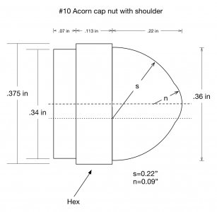
I am trying to make some #10 steel (1018) cap nuts with a shoulder that fits into a stabilizing counter bore. These are for 1930 Packard hinges. Standard cap nuts do not have the necessary shoulder.

My problem is that I have no idea how to machine the compound radius that makes up the dome of the nut.

I have the Sherline radius cutter, and have used it successfully on an earlier project with a simpler cut.

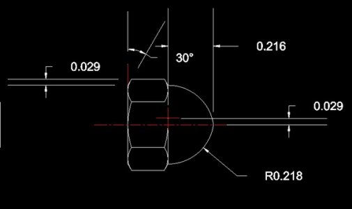
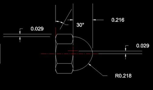
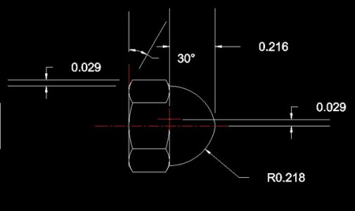
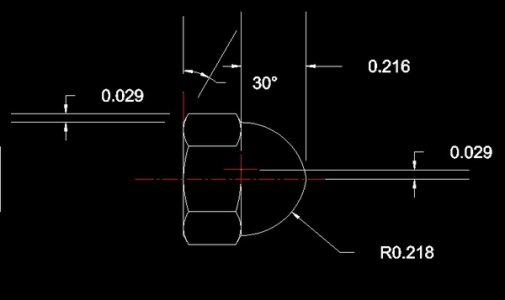
I have attached a diagram, modified from Machinery's Handbook, of the nut I am making. I removed the threads from the diagram for simplicity.

Any help will be greatly appreciated.

Thanks,

Tom
Packard hinge acorn nut.jpg
 
I think he is looking for the 2 radii so that the nut will look exactly like an original. A friend of mine occasionally makes Packard parts and they try to make them as close to original as possible.
 
If you cannot modify a existing nut as was suggested, which would be the simplest if you can, here is what I would do. Because this is a small nut I would grind a form tool. Draw your nut to scale, grind your tool with the the s & n radius. Grind the tool to be the negative image of your drawing from the center line to the start of your hex. Put about 7 degrees of negative rake under the nose of the tool. Turn as slow as you can with lots of cutting fluid. You can also rough out the radius first with a turning tool removing some of the material using the mk.1 eyeball method to reduce the chance of chatter on a small machine like yours. There are other ways of cutting radii using step over formulas and filing but for such a small nut I think you will be fine with just using the form tool. Here is a link from sherline that will give you a little idea.
http://www.sherline.com/grinding.htm
Darrell
 
The center of the radius is not on center according to McMaster's cad drawing, the radius is .218" and the center point -.029" in X and - .216" in Z. Set your radius tool .218" R, center it and move the cross slide .029" away from you, keep moving the carriage towards the chuck until you reach .216" or have completed the full profile.

The chamfers on the hex are 30º so plunge straight in with an external 60º threading tool, the depth of the sharp "V" is .029", part to length flip and drill and tap.
Good luck

jfj1h5.jpg

jfj1h5.jpg
 
The center of the radius is not on center according to McMaster's cad drawing, the radius is .218" and the center point -.029" in X and - .216" in Z. Set your radius tool .218" R, center it and move the cross slide .029" away from you, keep moving the carriage towards the chuck until you reach .216" or have completed the full profile.

The chamfers on the hex are 30º so plunge straight in with an external 60º threading tool, the depth of the sharp "V" is .029", part to length flip and drill and tap.
Good luck

jfj1h5.jpg
The ops print shows two different radii, at least that is how I am interpreting it. Sort of a dimple on top of the larger radius unlike the McMaster Carr version. It would require additional set ups with the radius cutter. I failed to notice the op said he had a radius cutter hence my form tool idea.

jfj1h5.jpg
 
The OP image was basically the design from the Machinery Handbook. I'm not sure if this was because that was what he found as the original Packard hinges or just what he found in the handbook.
 
The ops print shows two different radii, at least that is how I am interpreting it. Sort of a dimple on top of the larger radius unlike the McMaster Carr version. It would require additional set ups with the radius cutter. I failed to notice the op said he had a radius cutter hence my form tool idea.
I didn't see the link to that drawing at first, what he wants will take much more setup time with a radius attachment, having 2 radii per part with centers in different locations, the original parts were surely done in a screw machine with a form tool. Quite easily doable but fussy set up.
I have never used a radius attachment, do they have stops?
 
I haven't used one either:encourage: that is why I hoped you had a idea. We were both on the same page just different paragraphs!:clown:

Darrell
 
I haven't used one either:encourage: that is why I hoped you had a idea. We were both on the same page just different paragraphs!:clown:

Darrell
I could set up and program that in an hour on a CNC lathe. Doing it manually would be a bit more time consuming, if one has the time however go for it, they will certainly learn something from the experience.
 
Back
Top