- Joined
- Aug 7, 2018
- Messages
- 668
Hi Guys,
I know that some of you like projects, and tools ! So I thought I would do a little write up on how to design and make your own "Kant" style clamps.
These clamps are quite unique in so much that they behave very much like a vise. Unlike an ordinary "G" clamp they don't twist when being tightened up, in fact they can exert two or three times the force than can be achieved with a "G" clamp of the same size.
The design is quite flexible. You can make them from various materials, I made mine from steel plate, you could use aluminum or brass, or even plastic sheet material.
This project requires some turning and threading, but little else.
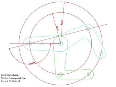
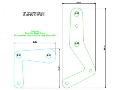
The picture above shows the basic layout of the Kant clamp. Notice that all the holes fall on the diameter of two concentric circles.
In this drawing the circles are 22 mm apart. To make larger or smaller clamps just scale the circles. The Odd hole is for a spacer.
You will need to turn this spacer down so that it clears the screw when the clamp is fully closed. The other spacer fits in the knee of the longer side piece.
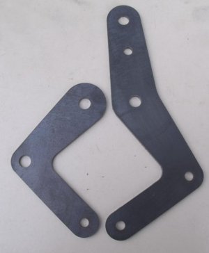
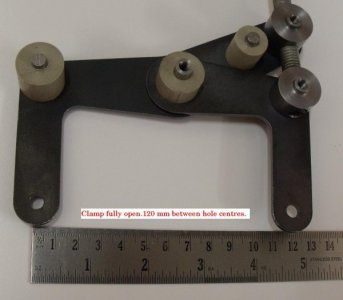
This is a picture of the side frames made according to the drawing. The pivot holes, larger ones are 8 mm diameter and the small ones 6 mm diameter.
You need two of each for each clamp. These were made from 3 mm laser cut plate. The original ones were cardboard templates.
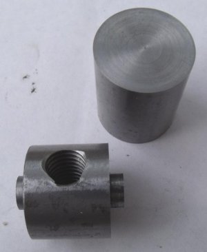
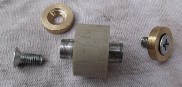
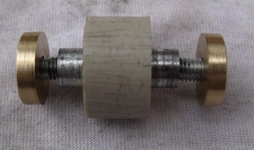
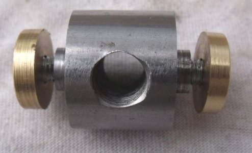
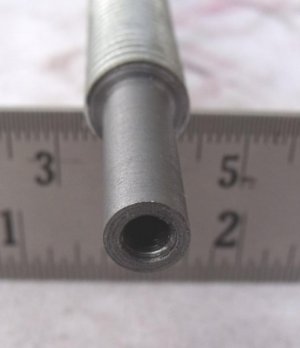
The nuts for the screw was a simple piece of turned bar with a M8 threaded hole. You need two of these nuts. The spigots on either side were turned so that they fitted into the 8 mm holes in the side plates. You can set the spacing between the side frames to what ever you like as long as you have room for the clamp screw.
I drilled each end and threaded for M5 CSK screws.
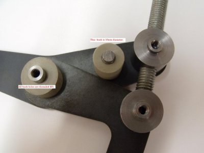
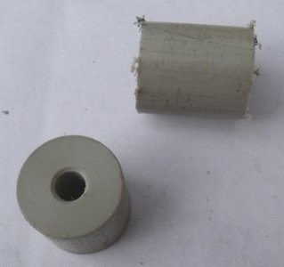
You also need to make some spacers. I made mine from PVC bar with a short length of 6 mm steel rod pressed through and pressed into the side frame. The laser cut holes were a quite tight fit on the 6 mm rod. But since they are only there to support the side frames it doesn't matter.
At this point I'm going to take a meal break. I'll continue later.
I know that some of you like projects, and tools ! So I thought I would do a little write up on how to design and make your own "Kant" style clamps.
These clamps are quite unique in so much that they behave very much like a vise. Unlike an ordinary "G" clamp they don't twist when being tightened up, in fact they can exert two or three times the force than can be achieved with a "G" clamp of the same size.
The design is quite flexible. You can make them from various materials, I made mine from steel plate, you could use aluminum or brass, or even plastic sheet material.
This project requires some turning and threading, but little else.

The picture above shows the basic layout of the Kant clamp. Notice that all the holes fall on the diameter of two concentric circles.
In this drawing the circles are 22 mm apart. To make larger or smaller clamps just scale the circles. The Odd hole is for a spacer.
You will need to turn this spacer down so that it clears the screw when the clamp is fully closed. The other spacer fits in the knee of the longer side piece.

This is a picture of the side frames made according to the drawing. The pivot holes, larger ones are 8 mm diameter and the small ones 6 mm diameter.
You need two of each for each clamp. These were made from 3 mm laser cut plate. The original ones were cardboard templates.

The nuts for the screw was a simple piece of turned bar with a M8 threaded hole. You need two of these nuts. The spigots on either side were turned so that they fitted into the 8 mm holes in the side plates. You can set the spacing between the side frames to what ever you like as long as you have room for the clamp screw.
I drilled each end and threaded for M5 CSK screws.
You also need to make some spacers. I made mine from PVC bar with a short length of 6 mm steel rod pressed through and pressed into the side frame. The laser cut holes were a quite tight fit on the 6 mm rod. But since they are only there to support the side frames it doesn't matter.

At this point I'm going to take a meal break. I'll continue later.


