Micrometer calibration adjustment

clueless

Registered
Registered
Joined
Dec 20, 2019
Messages
15
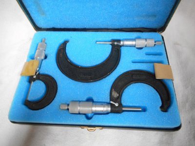
I acquired an older set of outside mechanical micrometers made by the (now defunct) New Britain Tool Company (a brand under the Litton Tool Company), once sold through NAPA, probably in the 1970's. They appear to be in decent overall shape and still in the original storage box. There is no documentation other than the "New Britain" label on the outside of the box and on the tools themselves it says "New Britain Made in USA", but no part numbers, etc..

I'd like to adjust the calibration setting on a couple of them, but these are not made like most micrometers that I'm familiar with. They have no hole for an adjustment wrench (and no wrench), and the thimble body is a one piece type (no two-piece friction adjustment). So how do you adjust them? I searched but wasn't able to find any information about these specifically online; apparently they weren't very popular because I did not see any mention of them anywhere.

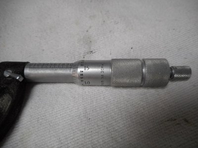
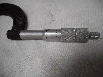
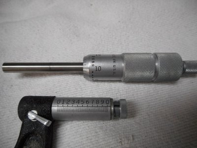
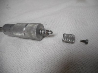
Here are some pics, anyone know how to adjust this type?
001.JPG003.JPG002.JPG005.JPG008.JPG
 
Should be a threaded adjustment nut on the back of the rods .
 
I suspect that the two knurled sections on the barrel unscrew to reveal the adjustment.
 
Thanks for the replies. The thimble ("two knurled sections") appears to be only one piece and not two, so the knurled areas are on the same solid piece and do not separate.

I saw something online about clamping the spindle in a soft jaw vice and unscrewing the thimble from it. However it would not unscrew. I put as much force as I felt was safe without damaging things, but nothing moved.

There must be a way to separate the spindle and thimble, or otherwise adjust it, but I have not been able to figure out how. Appreciate any further info about this design.
 
Hard to see by the pic , but is the nut split on the back of the rod ?
 
Hard to see by the pic , but is the nut split on the back of the rod ?
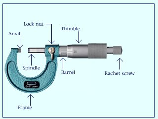
I'm not certain where you are referring to. I will use the first illustration (below) to reference the names of the various components.

fig 4_1.jpg

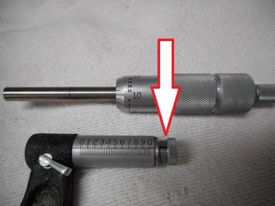
If you mean the threaded part shown by the arrow (second pic below), it is to adjust the tension between the spindle and barrel, for preferred resistance during operation of the thimble. That threaded collar is split, however this has no effect on calibration.

005 - Copy.JPG

Also, there is no adjustment at the anvil end, as found on some micrometers.
 
Last edited:
See if there is an allen head or slotted screw down where the ratchet screw came from.
 
Last edited:
Se if there is an allen head or slotted screw down where the ratchet screw came from.
I had the same thought. Unfortunately there is not. The ratchet is secured to the thimble by the tiny screw (shown in earlier pic). That little screw fits a blind threaded hole on the end of the thimble.

I'm thinking it is possible that the thimble is just threaded onto the spindle but has become corroded/frozen solid (why I wasn't able to move it on this one before). I'll attempt to remove it on some of the others and see if I get a different result. But I hate forcing a precision instrument to free it up.

They all work very well, just some of them are a two or three thousands off calibration. There is a fourth larger one in the lower tray beneath the ones I pictured before, so it is a nice set that I got for free. And the only other thing I have is a couple of vernier calipers, so I'd like to use them.
 
It may be left-hand threads. There is a place for standards in the case.
 
Back
Top