Mike's 6-Axis Articulated Robot

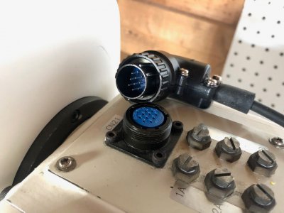
A quick check last night informed me that the motor power cable is not 1:1. So that sucks.

I have to ohm out the connections at the controller and likely rewire the controller side of the power cable.
 
Yeah, those lost interrupt/race conditions will get you every time. That's the real killer of coding at this level. Debugging those types of interactions is a really pain. Glad you found some help.
Yeah, I'm not a great programmer and this low level micro controller code is tough for me. Having fun with it though
 
Yeah, I'm not a great programmer and this low level micro controller code is tough for me. Having fun with it though
It's tough, you need a sense for it which is just a matter of time learning it. But you have to ask yourself for every line of code, can this get messed up by an interrupt? A = A + 1 is sensitive if there is an interrupt that can change the value of A. The other thing you get into is timing and latency, how long can something go ignored (such as interrupts disabled, or processing a different interrupt) before it causes an issue?
 
A quick check last night informed me that the motor power cable is not 1:1. So that sucks.

I have to ohm out the connections at the controller and likely rewire the controller side of the power cable.

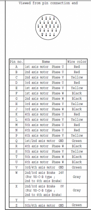
So I was a bit premature in stating this. The controller has a non sequential pinning, but so does the robot. The cable seems to work out straight thru, which is good news, because that how I wired it.

1646920692744.png

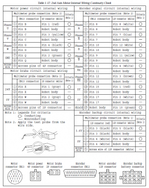
The maintenance manual includes several pages of worksheets to verify continuity in the robot and helps check the pinning. With the robot cables connected, I am going through each of these worksheets and verifying the connections. So good so far on J2, J3, and J4. I'm also learning my way around the control box which will be necessary.

1646920873058.png

Finally, I was amazed, but the controller ROM backup battery still has 3.05V on it (nominal is 3V). There is a slim but not impossible chance that it has never died and the controller is still backed up. We will have to see once I can get it powered on.
 
I am dabbling in Sherline CNC and find that challenging. Robotics seems so far above that. Curious, what is your background that you can dig into projects like this? What a challenge.
 
I am dabbling in Sherline CNC and find that challenging. Robotics seems so far above that. Curious, what is your background that you can dig into projects like this? What a challenge.
I started with a Sherline CNC at the end of high school and graduated to a G0704 CNC which I built several control cabinets for over the years.

Studied mechanical and electrical engineering in college and went into industrial automation with a focus in motion control and AC servo technology. Was always enamored with industrial robots and started studying the math behind the motion control in my free time (very complicated stuff, really struggled to learn it). Unfortunately due to my mechanical and controls background, I was never happy with just looking at the math, a 3D model simulation, or a crappy robot using hobby servos. So I knew a place that sold robots and occasionally they come up cheap. The first one I found was a 4 axis SCARA and I bought it without knowing what I would get myself into. That one required me to use a PLC and design custom feedback interface boards to run it. It was cool but I always wanted a 6 axis one. This one eventually came up and I snatched it up.

I have *hopefully* a bit of an easier time with this one because I can run it on the original control if nothing is broken. I may optionally also get it running on a Rockwell PLC with Rockwell servo drives (hence the feedback interface programming above) but I hope I don't have to.

So background in engineering, lots of professional experience in AC servos and motion control, and a hobby in robotics.

I've found robotics to have a significantly higher barrier to entry than CNC.
 
Denso passed me two more files which I will share here. A list of Error Codes and a list of replacement part numbers.
 

Attachments

  • RB-P-5(E)_090617.pdf
    376.5 KB · Views: 2
  • RC3 Error Codes.pdf
    657.6 KB · Views: 1
Got a big order from Digikey. The main items were the Lithium Thoinyl Chloride primary batteries for the controller memory backup and robot actuator encoder absolute position backup.

I could have probably just replaced the batteries on the existing board, but the dimensions varied just a bit, and it was in my interest to have a few spare boards to facilitate swapping batteries in the future.

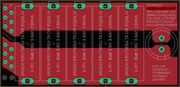
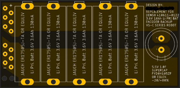
I was able to get some PCBs designed based on the original board in Autodesk Eagle in a couple hours. I'm super rusty in this software as I haven't used it in 2 years, but I was able to make custom footprints for all the components and layout a board pretty easily. My board will be a bit larger than the original board as there is enough space in the robot and the new batteries were each 0.5mm larger in diameter than the old ones. This stacked up and required a slightly larger board. A new 5.5V 1.0F supercapacitor was sourced as well, bringing the total cost for the board up to $45 (batteries. capacitor, mini-mate connector) plus the cost of the PCB ($31 for 10 boards, includes $20 shipping).

View inside Eagle:
1647215412809.png

Example View, Black Soldermask, White Text, Gold Pads:
1647215460365.png

These should be here within 2 weeks or so. Need to get an electrician to install some 240V and 208V outlets in the basement.
 
Took just a couple weeks to get my new PCBs shipped the cheapest method. Think 10 boards cost me $20 shipped. They are beautiful.
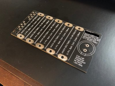
image207_LI.jpg

Here is a mockup of the 5 battery cells. They are just slightly wider than the old batteries.
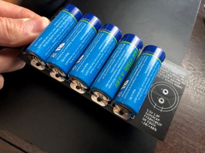
image208_LI.jpg

Transferred the wiring harness from the robot's original PCB to the new one. I have spare connectors, pins, and a crimping tool, so I will make 1 or 2 spare boards to facilitate a swap a few years from now. The supercapacitor is new (5.5V 1.0F yikes!) .

I'm holding off on soldering the batteries until the robot is ready to be powered on. There was some clear shrink wrap over the old battery board that I'll need to replace with something equivalent.
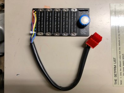
image211_LI.jpg

New board with batteries ready to be soldered on.
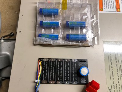
image212_LI.jpg

I have an electrician scheduled to install 240V and 120V outlets in my basement. I was going to do it myself, but the cost of the materials from Menards was almost as much as the electrician wanted for parts and labor. I still need to pick up the 240V to 208V transformer from a buddy back where I used to live. That will require both primary and secondary fusing, so I'll need a simple interconnect box to go with it. I'm thinking I''ll attach the transformer, interconnect fuse box, and 208V outlet to a plywood skid that I can hang on the wall next to one of the 240V outlets. Then the converter is portable as needed.

It took me a LOT of effort, but I finally got the correct connector for the end of arm tooling. I had originally purchased a DENSO original, but it was for the dust proof robot option only and did not fit this one. I could not locate the correct DENSO part for my robot, but I found a, now obsolete, connector made by DDK who supplied the connectors to DENSO. There are only something like 30 left in stock worldwide as far as I could tell. Not cheap either, but necessary to hook up end of arm tooling.
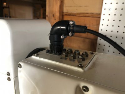
image213.jpg


image214.jpg

Need to keep cleaning all the gearboxes. Once power is available, I hope I can power the original control up and run the robot. There are a million and one things that could go wrong, but I am optimistic.
 
Been stalled on this, but finally getting ready to take some steps forward.

I am picking up a 240V -> 208V buck transformer (1 phase 2 kVA) which will get my supply power down to the required 210V +/- 10% for the robot controller. An electrician is coming early next week to install 240V and 120V outlets in the basement for the lathe, mill, SCARA robot, Denso robot, and one spare hookup.

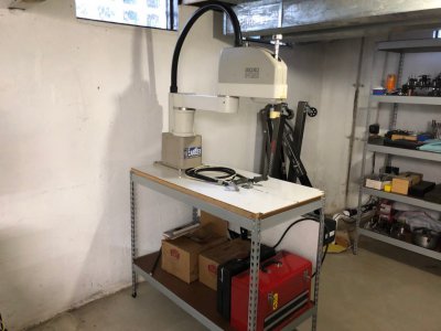
I got the SCARA robot lifted onto the table I have for it (it weighs about 140lbs and was a bear to get up there. Didn't feel like using the engine hoist.

image215.jpg

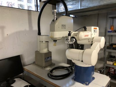
Fun shot with the two robots side by side.

image216.jpg

I think the next steps will be to build a mobile carrier for the stepdown transformer and the associated primary and secondary fusing. Then build a power cable for the Denso robot controller. Finally, I should be able to (*hopefully*) power on the controller, replace the encoder battery, replace the controller battery, and start dealing with whatever error messages are displayed. There are a ton of unknowns here, but in the best case, I only need to zero the encoders, recalibrate the robot, and clear the controller memory.
 
Back
Top