-
Welcome back Guest! Did you know you can mentor other members here at H-M? If not, please check out our Relaunch of Hobby Machinist Mentoring Program!
You are using an out of date browser. It may not display this or other websites correctly.
You should upgrade or use an alternative browser.
You should upgrade or use an alternative browser.
Mike's 6-Axis Articulated Robot
- Thread starter macardoso
- Start date
- Joined
- Mar 26, 2018
- Messages
- 2,724
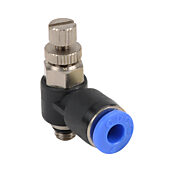
Got a pile of pneumatic fittings on order from AutomationDirect. That should let me connect my compressor to the robot and actuate the internal solenoid valves and the gripper I bought. The robot has all metric push to connect ports so I needed to get matching fittings. I also picked up speed control valves for the gripper so it has a soft close function.
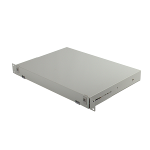
I'll need some sort of junction box for all the IO wiring that is needed. A 1U server rack sized box would be perfect, but those are $250 new. I intend to rack mount the controller under my workbench.
The J2 harmonic drive gearbox is still not sounding wonderful. I need to open it up again and remove the whole gearbox for cleaning. Looking at pictures online, I think I see how I can remove the whole thing. I would prefer to clean in place, but I'll do whatever I need to I guess. There is one for sale on eBay Korea, but it is $500 used, ouch.
I am likely going to start writing programs to test out all the different instructions. Once the pneumatics are set up and I can machine an adapter for the gripper, I'd like to see it assemble some Legos or another moderately complex task like that.

I'll need some sort of junction box for all the IO wiring that is needed. A 1U server rack sized box would be perfect, but those are $250 new. I intend to rack mount the controller under my workbench.

The J2 harmonic drive gearbox is still not sounding wonderful. I need to open it up again and remove the whole gearbox for cleaning. Looking at pictures online, I think I see how I can remove the whole thing. I would prefer to clean in place, but I'll do whatever I need to I guess. There is one for sale on eBay Korea, but it is $500 used, ouch.

I am likely going to start writing programs to test out all the different instructions. Once the pneumatics are set up and I can machine an adapter for the gripper, I'd like to see it assemble some Legos or another moderately complex task like that.
- Joined
- Aug 6, 2015
- Messages
- 3,885
Wrote a quick program last night to send to the guy at Denso who helped me out so much.
It is very cool that you did that. I work in a Support environment and it is refreshing to get something like this. When you are always working on resolving problems or dealing with customer's escalations, a positive note on a job well done, or appreciation of the help provide, goes a long way.
- Joined
- Jul 20, 2012
- Messages
- 1,238
It is so awesome you are taking the time to post detailed updates on this!
- Joined
- Mar 26, 2018
- Messages
- 2,724
I took a little time yesterday to clean up my workspace and moved the control box under the workbench. I am now doing a poor installation by running the robot power and encoder cables in parallel, as well as bringing the encoder cable past the transformer. I noticed a significant increase in audible noise coming from the robot as well as a number of errors during the power on calibration. I can eventually get it to calibrate, but not usually on the first try anymore. This tells me the robot is susceptible to radiated noise and the motor cable and encoder cable shields aren't giving sufficient coverage. I have a few tricks I was to do, but at the end of the day, I'll need to be smart about the cable routing.
I also decided to dive back into the J2 gearbox. This time I was determined to get it apart for cleaning. I got the motor removed and was immediately shocked by how brown my new white grease was. Most got scooped out to access the bolts on the flexspline. I tried pulling it by hand again, but got nowhere. Then I put the motor/wave generator back on hoping that the wave generator would pull the flexspline out with it. This did not work either.
Looking at the assembly, I could see that this harmonic drive was a type that had an integral crossed roller bearing. Thus this was completely supporting the upper arm. Unlike the other gearboxes, this did not have threaded ejector holes to install screws into to push out the flexspline. This is why I struggled with it the first time.
I gave it some careful thought and made a bold choice to remove the 8 bolts holding the upper arm to the gearbox. This would give me access to the backside of the gearbox, and hopefully a way to remove the flexspline. I prepared a place to rest the arm once it was removed and took off the last remaining bolts. I used the same 8 bolts that held the arm on to thread deeper through their mounting holes and push the flexspline from the backside. Gently tightening the bolts pushed the cup straight out. There are 6 dowel pins that align the cup that required some care in how it was removed. These also contributed to the difficulty in removal earlier. After feeling how much pressure was needed on the bolts, there is no way I ever would have pulled this by hand.
The upper arm was less heavy than expected and was easy to place next to the base.
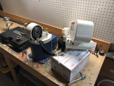
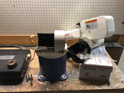
The arm itself has a small centering boss and 8 through holes to mount it.
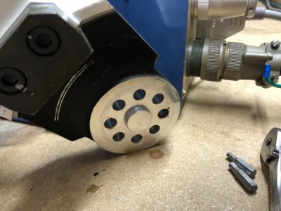
I was never able to clean back here and found the gearbox filled with mud brown/black old grease which was definitely gritty - not good.
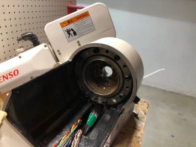
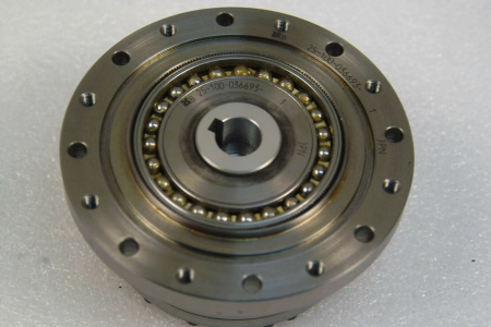
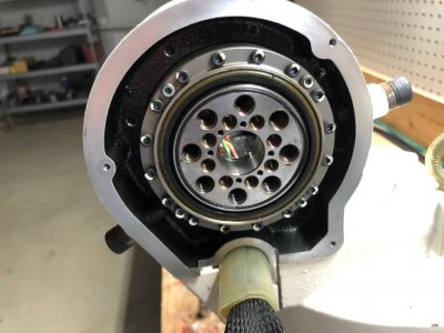
I think this shot is pretty cool. The silvery and black outer ring is the aluminum casting of the robot. Then the entire steel chunk in the middle is the harmonic drive gearbox with integral output bearing. If you look at the center bore, you can see how thick that output flange is. Along the perimeter is a crossed roller bearing. Crossed roller bearings are designed for slow speeds, high loads, and extreme stiffness and accuracy. They are very expensive and reserved for high end motion control applications. There is a lot of drag from spinning this bearing alone. You can tell it is highly preloaded.
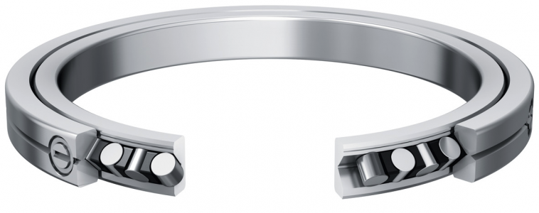
Here is a sample catalog image of this kind of bearing. The outer race is usually split and preload is achieved by squeezing the outer races together with bolts.
I removed all the old grease and scrubbed down all the teeth of the ring gear and flex spline with a toothbrush and various cleaning solutions. The flexspline also got a vigorous bath in WD40 and 99% isopropyl alcohol to get all the grit and old grease removed. I could see a substantial amount of wear on the flexspline teeth. It didn't show up on camera well, but the crests of the teeth were polished to a silvery sheen where all the other gearboxes appeared extremely matte.
Everything was regreased and prepared to be reassembled. I'll do that tonight. Can't afford to replace this gearbox, so I'm hoping that this cleaning will get it running smoother and give it some additional life.
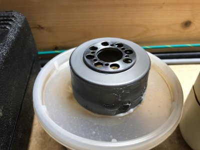
The backside of the gearbox will get packed fully with grease before I put the flexspline back in.
I also decided to dive back into the J2 gearbox. This time I was determined to get it apart for cleaning. I got the motor removed and was immediately shocked by how brown my new white grease was. Most got scooped out to access the bolts on the flexspline. I tried pulling it by hand again, but got nowhere. Then I put the motor/wave generator back on hoping that the wave generator would pull the flexspline out with it. This did not work either.
Looking at the assembly, I could see that this harmonic drive was a type that had an integral crossed roller bearing. Thus this was completely supporting the upper arm. Unlike the other gearboxes, this did not have threaded ejector holes to install screws into to push out the flexspline. This is why I struggled with it the first time.
I gave it some careful thought and made a bold choice to remove the 8 bolts holding the upper arm to the gearbox. This would give me access to the backside of the gearbox, and hopefully a way to remove the flexspline. I prepared a place to rest the arm once it was removed and took off the last remaining bolts. I used the same 8 bolts that held the arm on to thread deeper through their mounting holes and push the flexspline from the backside. Gently tightening the bolts pushed the cup straight out. There are 6 dowel pins that align the cup that required some care in how it was removed. These also contributed to the difficulty in removal earlier. After feeling how much pressure was needed on the bolts, there is no way I ever would have pulled this by hand.
The upper arm was less heavy than expected and was easy to place next to the base.


The arm itself has a small centering boss and 8 through holes to mount it.

I was never able to clean back here and found the gearbox filled with mud brown/black old grease which was definitely gritty - not good.

I think this shot is pretty cool. The silvery and black outer ring is the aluminum casting of the robot. Then the entire steel chunk in the middle is the harmonic drive gearbox with integral output bearing. If you look at the center bore, you can see how thick that output flange is. Along the perimeter is a crossed roller bearing. Crossed roller bearings are designed for slow speeds, high loads, and extreme stiffness and accuracy. They are very expensive and reserved for high end motion control applications. There is a lot of drag from spinning this bearing alone. You can tell it is highly preloaded.

Here is a sample catalog image of this kind of bearing. The outer race is usually split and preload is achieved by squeezing the outer races together with bolts.

I removed all the old grease and scrubbed down all the teeth of the ring gear and flex spline with a toothbrush and various cleaning solutions. The flexspline also got a vigorous bath in WD40 and 99% isopropyl alcohol to get all the grit and old grease removed. I could see a substantial amount of wear on the flexspline teeth. It didn't show up on camera well, but the crests of the teeth were polished to a silvery sheen where all the other gearboxes appeared extremely matte.
Everything was regreased and prepared to be reassembled. I'll do that tonight. Can't afford to replace this gearbox, so I'm hoping that this cleaning will get it running smoother and give it some additional life.

The backside of the gearbox will get packed fully with grease before I put the flexspline back in.

- Joined
- Mar 26, 2018
- Messages
- 2,724
I should add that the post above was very risky in terms of messing up the robot calibration. The robot has very carefully measured angles from the factory that allow it to make accurate motion in cartesian space (straight lines, arcs, etc.). If I were to move a hardstop for example, the robot would never move correctly again.
These calibration values can be overwritten, but I do not have the inspection tools or knowledge to measure the joint angles at hardstop down to the ten thousandth of a degree as they have been done at the factory.
I felt this risk was justified due to the poor condition of the gearbox. I could actually hear it grinding as it moved. The motion of the end of the arm was also jerky whenever J2 had a contribution to the motion. I hope I have given the gearbox a good chance to enjoy its golden years.
In terms of reassembly, I did not adjust the hardstops so those should be OK. The gearbox has a tight fit to the robot base casting which should self center very accurately. The arm has a tight fit to that centering boss on the output flange which should also self center accurately. The angle of the arm to the gearbox flange does not matter as it will be accounted for in the new CALSET against the hardstop. The motor was disconnected from the battery, so an encoder reset procedure needs to be completed on J2 and a single axis CALSET done on the joint as well. Fingers crossed I did not mess anything up and this will have been a positive experience.
- Joined
- Jan 2, 2014
- Messages
- 8,852
Two comments:
1) Thanks for showing that cut-away view of the "crossed roller bearing"!
I had not heard the term or seen one before.... and any day I can learn something new it's a good day.
2) about the "bold choice" and "risky" operation......
It is very clear that this project is in very capable hands!
Your deep understanding and methodical approach is not only impressive, but it's made this thread thought provoking and enjoyable to read.
Keep up the great work!
Much respect!
Brian
- Joined
- Mar 26, 2018
- Messages
- 2,724
Gearbox is greased and back together. Took me two attempts since I forgot a plastic cover that has to be installed before the arm is bolted back on.
When I was figuring out how to remove the flex spline cup, I had loosened the 8 bolts holding the harmonic drive to the robot's casting. At this point I was not yet aware that the output bearing was integral to the harmonic drive (it is not in J3-5). The whole arm started to lean sideways as I loosened the last bolt. I did tighten everything back down, but I thought it might be prudent to double check that I did not marr the mounting surfaces of the casting.
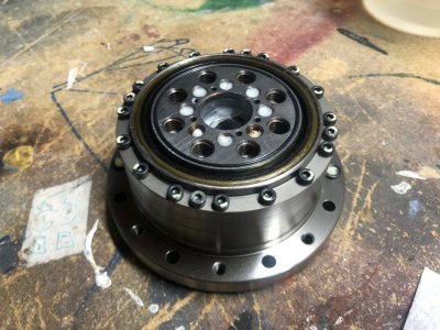
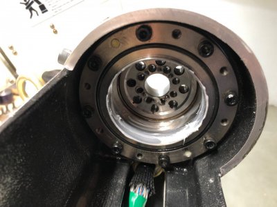
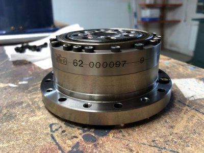
This image is kinda cool. I think there might be (2) crossed roller bearings. There is an obvious split line down the middle of the text, but also two harder to see split lines above and below the text, making (4) total rings stacked. I think the hard to see split lines are the two halves of each crossed roller bearing compressed to generate preload. The excessive number of bolts along the perimeter are used to compress these rings.
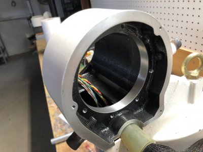
Here is the housing where the harmonic drive mounts.
And the arm back together with the side cover removed.
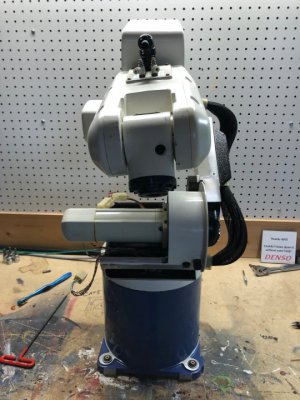
I performed the encoder reset procedure and the single axis CALSET procedure. I was very happy to see the robot completing the programs I had already entered with near perfect precision to before. At most, there was a half mm deviation at the end of the arm which I think is to be expected. Robots in general are not meant to be particularly accurate in terms of positioning in the global absolute space, but they are exceptionally repeatable in moving to taught positions.
I wrote a simple 4 line program to cycle the J2 joint from end limit to end limit and let that cycle for several hours at 10% speed. The gearbox was initially very noisy but that settled down as the grease worked itself in. I may have overfilled the gearbox with grease a bit, but I left the bleed port open and it spat out a bit of excess. After 3 hours or so, I checked on it and the gearbox was nice and quiet, no grinding sounds.
The motion remains a bit jerky when J2 is contributing significantly to the motion, and I have a feeling that this is a function of the wear on the gearbox. A small amount of compliance in the gearbox amplifies both servo motor vibrations and bubbles/grease between teeth of the gearbox. View this 24" from the joint when the arm is fully outstretched and small arc-second/arc-minute sized vibrations become significant movements. This does not affect positioning accuracy and is not noticeable at anything above 25%. At the end of the day, this is a $40k machine that I picked up for $400 and it is only for hobby use, so whatever. I bet a gearbox swap would fix it if it really starts bothering me.
As I was messing around with the robot in manual jog mode late last night I kept hearing clicking from the J2 motor followed by erratic jerking of the joint and really nasty sounds. Didn't take me long to figure out that the J2 motor electromechanical brake was closing while the motor was running. I need to troubleshoot this, but I have a feeling it is from the 2 pin connector on the motor that I accidentally broke the retaining clip on. I have the connector taped shut, but I bet the contacts are making poor connection with all the mating cycles they just got. I have spare crimp contacts so I should pick up some connector bodies and replace the whole setup. I'm fairly confident the controller is still working OK since the J2 and J3 motors share the same circuit from the controller and the same conductor in the motor power cable, and J3 is working fine.
My order of connectors for the controller battery came in today from eBay. I had to buy a full lot since these are discontinued and no major electronics company (Digikey, Mouser, Newark, etc.) carries them. The crimp contacts are coming from Mouser in the $3 shipping option. They might show up next year. Amusingly, if I stick to replacing the battery every two years and I never reuse the connectors, I'll have enough to last me until 2084. If I'm still alive (now that's a depressing thought!).
When I was figuring out how to remove the flex spline cup, I had loosened the 8 bolts holding the harmonic drive to the robot's casting. At this point I was not yet aware that the output bearing was integral to the harmonic drive (it is not in J3-5). The whole arm started to lean sideways as I loosened the last bolt. I did tighten everything back down, but I thought it might be prudent to double check that I did not marr the mounting surfaces of the casting.

This image is kinda cool. I think there might be (2) crossed roller bearings. There is an obvious split line down the middle of the text, but also two harder to see split lines above and below the text, making (4) total rings stacked. I think the hard to see split lines are the two halves of each crossed roller bearing compressed to generate preload. The excessive number of bolts along the perimeter are used to compress these rings.

Here is the housing where the harmonic drive mounts.

And the arm back together with the side cover removed.

I performed the encoder reset procedure and the single axis CALSET procedure. I was very happy to see the robot completing the programs I had already entered with near perfect precision to before. At most, there was a half mm deviation at the end of the arm which I think is to be expected. Robots in general are not meant to be particularly accurate in terms of positioning in the global absolute space, but they are exceptionally repeatable in moving to taught positions.
I wrote a simple 4 line program to cycle the J2 joint from end limit to end limit and let that cycle for several hours at 10% speed. The gearbox was initially very noisy but that settled down as the grease worked itself in. I may have overfilled the gearbox with grease a bit, but I left the bleed port open and it spat out a bit of excess. After 3 hours or so, I checked on it and the gearbox was nice and quiet, no grinding sounds.
The motion remains a bit jerky when J2 is contributing significantly to the motion, and I have a feeling that this is a function of the wear on the gearbox. A small amount of compliance in the gearbox amplifies both servo motor vibrations and bubbles/grease between teeth of the gearbox. View this 24" from the joint when the arm is fully outstretched and small arc-second/arc-minute sized vibrations become significant movements. This does not affect positioning accuracy and is not noticeable at anything above 25%. At the end of the day, this is a $40k machine that I picked up for $400 and it is only for hobby use, so whatever. I bet a gearbox swap would fix it if it really starts bothering me.
As I was messing around with the robot in manual jog mode late last night I kept hearing clicking from the J2 motor followed by erratic jerking of the joint and really nasty sounds. Didn't take me long to figure out that the J2 motor electromechanical brake was closing while the motor was running. I need to troubleshoot this, but I have a feeling it is from the 2 pin connector on the motor that I accidentally broke the retaining clip on. I have the connector taped shut, but I bet the contacts are making poor connection with all the mating cycles they just got. I have spare crimp contacts so I should pick up some connector bodies and replace the whole setup. I'm fairly confident the controller is still working OK since the J2 and J3 motors share the same circuit from the controller and the same conductor in the motor power cable, and J3 is working fine.
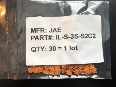
My order of connectors for the controller battery came in today from eBay. I had to buy a full lot since these are discontinued and no major electronics company (Digikey, Mouser, Newark, etc.) carries them. The crimp contacts are coming from Mouser in the $3 shipping option. They might show up next year. Amusingly, if I stick to replacing the battery every two years and I never reuse the connectors, I'll have enough to last me until 2084. If I'm still alive

- Joined
- Mar 26, 2018
- Messages
- 2,724
- Joined
- Mar 26, 2018
- Messages
- 2,724
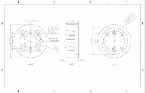
Well this was a dumb design... Whenever you do something "quick" in CAD, it is usually a mess. I thought I was accounting for the dimensions of the gripper which would leave enough room to get an allen wrench on the mounting bolts to attach the platter to the robot, but the gripper corners are facing the bolt holes and as such, I cannot access them with the wrench.Drew up a quick mount for the gripper in CAD.
I already did all the lathe work on this last night, so I'll have to see if I can salvage the design to be close to how it is now


