Alright, made some progress last night.
Ran a more thorough test last night of the encoder. Powered it on with the shaft in a known position and saved the serial data. The I rotated the shaft 2 rotations CCW when viewing the shaft face and tried my best to get it lined up.
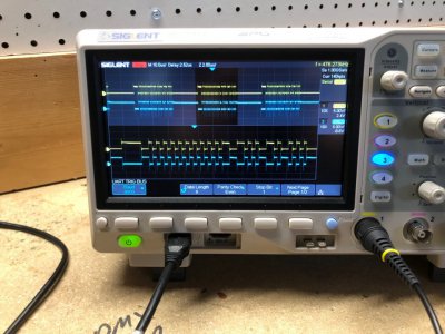
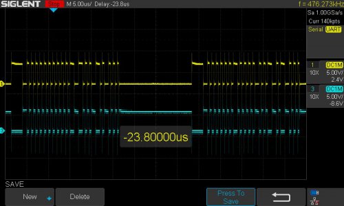
Here is the serial packets immediately after power on.
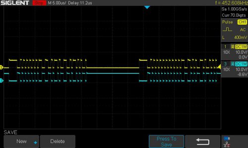
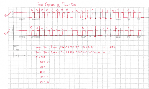
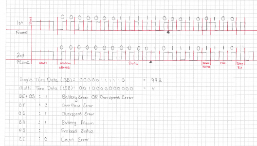
After decoding them, I can see I am at 1184 counts (of 2048) for the single turn data, and 5 revolutions on the multiturn data. OK, well does that make sense? The single turn data is absolute and does not require the battery to back it up. The zero count location should be aligned with the zero electrical degree position for commutation (or a known offset like 90*). So yes, a non-zero single turn value is expected at power on. What about that multiturn data? That should be battery backed and get reset after a power loss.
Well it turns out that the encoder has a supercapacitor that keeps the encoder powered for up to an hour after power loss to facilitate replacing the backup batteries. The capacitor is expected to age down to 15 minutes after 10 years (it's been 22.5

). So the multiturn counter didn't reset while I was preparing for this test.


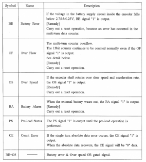
Also, take a quick note that the PS flag (Pre-Load Status) is set to 1 right now.
OK. So with the encoder powered, I manually rotated the shaft 2 revolutions CCW. Then I captured the serial data again and decoded it.
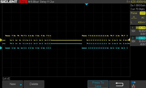
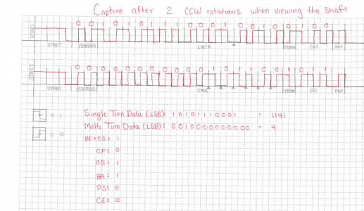
As expected, the single turn data is 1141 counts of 2048. This is very close to the starting single turn position of 1184. The multiturn counter has decremented to 4. I expected 3 so not sure about that... Maybe I did move it only 1 rev? Not positive.
Notice now that the PS bit is 0. This bit is indicating the the accuracy of the data is limited until the shaft has been disturbed by 2 degrees mechanical. Since I moved the shaft 2 full revolutions, this cleared the PS bit.
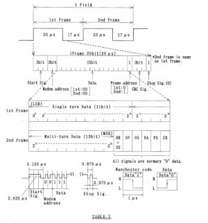
I'm not sure what "renews 5 bit absolute data to 11 bit absolute data" means. Not sure if this is the single turn or multiturn data. I'm assuming singe turn. If this is the case, there is a 2^6 (2^(11-5)) count (64 count) uncertainty in the single turn position right at start-up until the shaft has been disturbed. This could account for the difference in single turn counts between the two readings (1184 vs 1141) or that could have just been my inaccuracy in lining up the shaft exactly on the same mark.

I also figured out the CRC based on
@rabler previous post. This is a polynomial CRC. Specifically it is a 3 bit X^3 + x +1 (also known as a 1011 polynomial CRC). You can do the math by hand or use an
online calculator to generate a CRC from the data. This
online calculator even includes a provision to check the CRC after a simulated transmission. The CRC includes the ADDRESS, DATA, and FRAME fields, but not the START, STOP, or CRC fields (obviously, since this is what we are calculating).
This CRC is a highly efficient method of checking the data for random bit flips with an extremely low probability of one getting past. CRC codes are able to detect double bit flips. More robust methods like hamming codes provide more certainty in the error checking, and even on the fly error correction at the receiving end, but use more data for the error correction. This was obviously not desirable to the encoder designed as they wanted to broadcast the data as fast as possible and this meant small data packets. A CRC also provides more resiliency than a simpler checksum, which can only protect against a single bit flip.
If this were to be done with
Hamming Codes, the 36 bits of data would have needed to be broken into groups of 26 bits (Hamming(31,26)) and would have needed 70 bits to transmit the same data that this CRC scheme transmits in 50 bits. We can see that this CRC scheme is nearly 30% more efficient than Hamming codes.
I had one additional thing to look into. A new set of single and multiturn positions come over serial every 84us. This encoder also outputs quadrature encoder signals at an increased resolution of 2^13 bits (8192 counts per revolution). So if we choose to use both the serial data AND the raw encoder data, we can increase our usable resolution of the encoder, while remaining aware of the absolute position, and even cross checking the position data from two sources. Assuming the motor max speed of 5000rpm, each quadrature count arrives every 1.47us. This is much faster than the serial rate, giving us better tracking of the motor position. While a serial only solution would likely work, I think the final implementation of the encoder interface board should use this additional data.
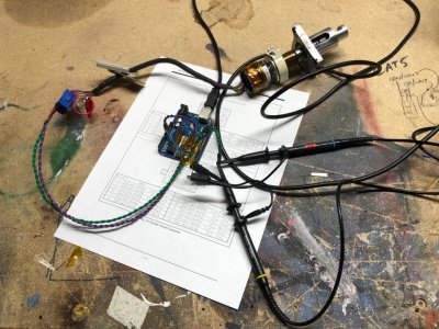
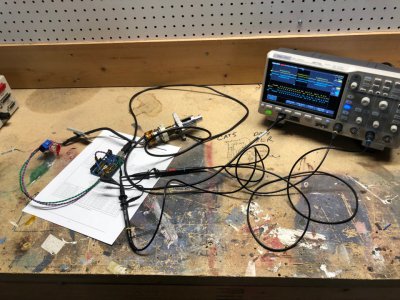
I also took a moment to hook up an AM25C32I RS422 Differential Line Receiver. I actually had exactly one left over from making the encoder interface boards from the last robot and also managed to find a small SOIC16 to DIP breakout board. Soldered it up real quick and it worked perfectly!
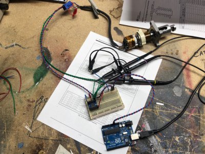
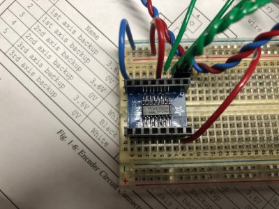
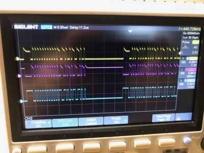
The yellow and pink traces are the differential RS422 inputs, and the blue trace is the 0-5V single ended signal coming out of the AM26C32I differential line receiver. This signal should be perfect for wiring into an arduino. Notice how much cleaner this signal looks too! I think I can use my UNO with software serial and a FTDI to read text to a serial monitor, or I can buy a Arduino Mega with 2 hardware serial ports. I don't think software serial supports manchester decoding, but the hardware serial seems to with a library.
 www.robot-forum.com


