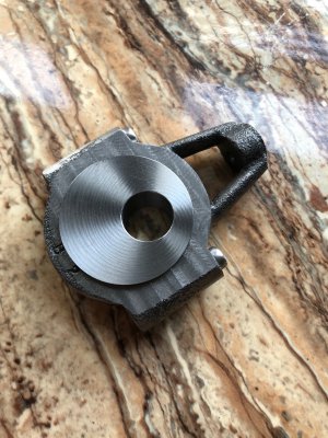
Whew! Made a big push on this yesterday and got the connecting rod done. We are in the process of packing the house for our move and this was the last thing I wanted to get done before the machines come out of the basement and got wrapped up to go on the truck. Took a vacation day off work to get a full uninterrupted day.
I had previously spent 2.5 hours on the first connecting rod before fumbling the keyboard on my CNC and crashing an endmill into the part. Then another 3 hours on this one, hand filing the general shape and facing the two sides of the split end of the rod to thickness and parallelism.
I found this part particularly tricky to fixture. There are no flat sides on it, the main shaft section is somewhat twisted and tapered, and when you do clamp it, the part sits crooked in the vise. Furthermore at ~8" long, this takes up a lot of space on my mill and requires work on both ends accurately clocked to eachother.
I opted for a poor man's compound angle vise. I placed a 3.5" drill press vise in my 4" milling vise, and a 2" tool makers vise in that one. This did 2 things. First it allowed me to dial in the part's orientation one axis at a time without affecting the orientation of other axes during adjustment. Second, it gave a fair bit of clearance above the table for the next operation. I'll explain why this was necessary when we get there.
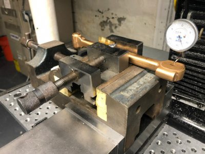
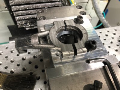
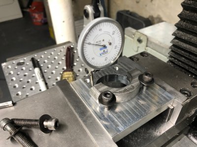
It took me most of the morning to get the part clamped securely and indicated true. The part is held in the tool makers vise using a pin and some shim stock to improve the clamping rigidity. A trick that I use a lot is to use a round object (in this case some 1/2" steel stock) on the moving jaw of the vise to grip on parts which have uneven or non-parallel faces. Without this, the moving jaw couldn't securely grip on the part. I then indicated the pitch of the part (about the X axis) first by tapping the tool makers vise in the jaw of the drill press vise. Then I securely tightened the drill press vise and started tapping it in the jaws of the milling vise to set the roll of the part (about the Y axis). The milling vise was then tightened securely. Finally the milling vise was rotated on the table surface to set the yaw of the part (about the Z axis). All indicator readings were made within 0.0005", probably excessive for a casting, but I didn't want any screw ups.
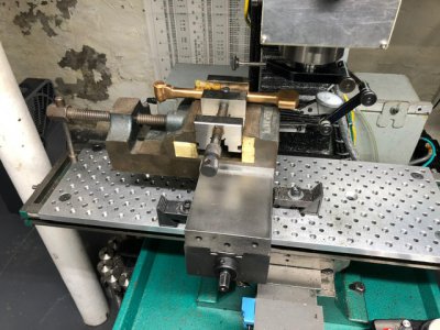
My mill has 9" of table to spindle clearance, which left no possibility of doing the end work on the cap with the part vertical. This required flipping the spindle 90 degrees on its side to access the side of the part. I took a lot of time to carefully position the fixture on the table to allow room for the end work on the one side, as well as all later operations from the vertical position in one setup. This unfortunately left extremely little room to work requiring a rather complicated setup to square the mill head to the face. I used the side of my precision granite square (less accurate, but still guaranteed square on the instrument certificate) to indicate off of. Once the spindle was square within 0.0002" TIR of a 2" swept circle, I could edge find the cap screw locations.
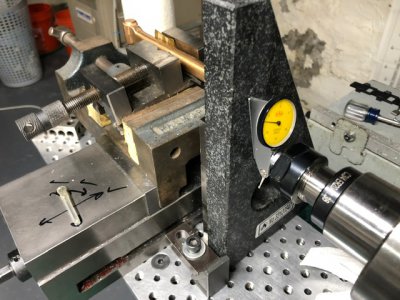
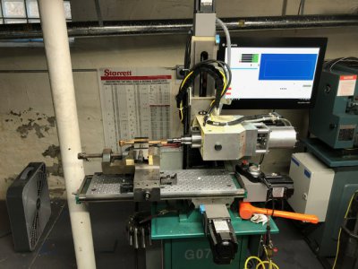
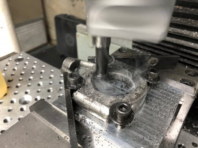
The screw holes were spotfaced, center drilled, clearance drilled (to half depth), and tap drilled through. Following that, a 3" 1/16" thick slitting saw was used to split the cap. I didn't get a picture of the slitting operation, but the tool makes an appearance later. At this low speed (150 rpm) and uneven loading (slightly eccentric slitting saw) the servo spindle struggles with the cut. It only consumes about 10% of the motor torque, but it would stall and surge significantly. Higher speeds and feeds actually do a lot to fix this problem.
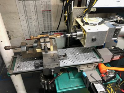
After slitting the tap drill holes were tapped. I wish I had done this before slitting since the tap raised a burr, but it wasn't the end of the world
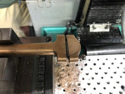
Using a tenths indicator and an optical flat, I precision edge found the split line for subsequent drilling. Joe Pie has a great YouTube video on this method. The cap was screwed back on and I used some sharp drills to open the hole up.
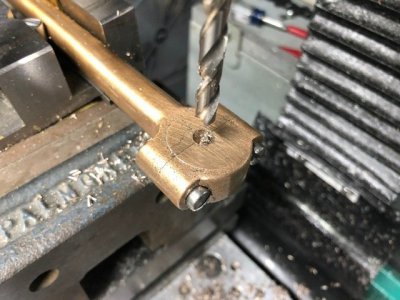
Thinking it might cut a bit more freely on this poorly supported part, I tried to expand the hold with a 3/8" 3F aluminum specific carbide endmill. Unfortunately it snagged immediately and destroyed the endmill. There's $40 down the drain. Fortunately the part was fine and I drilled the hole out to 3/8"
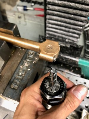
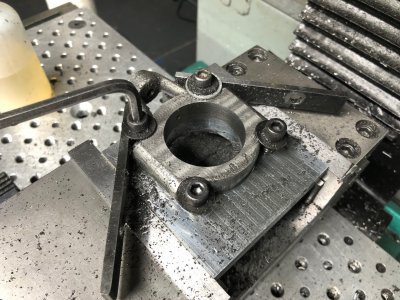
I then wrote a short multi-line MDI program on the CNC to repeatedly bore the hole and retract. I advanced the diameter 10 thou at a time. Final dimension was 0.5001" (.5000 target, reamed, no stated tolerance). The crank pin was turned to 0.4988"
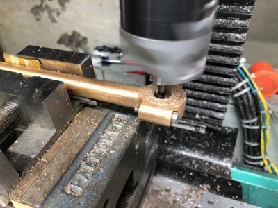
I test fit the crank shaft in-situ and the fit was perfect. Would not be able to easily line this up again to correct the bore once it was removed from the machine.
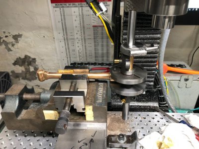
The other end was drilled and reamed to 0.3135" for a sliding fit to a 0.3125" pin. The prints called out facing both sides of this joint, plus a square bottomed slot with precision width and depth. The alignment to the other end is absolutely critical or the assembly will bind. For these reasons, I opted to not move the part from the fixture at all and complete all the remaining operations with the slitting saw. This guarantees alignment, although the cutting process was VERY slow.
I took about 45 minutes to quadruple check all my Z position math for the slitting saw since I'd be creating finished dimensions in one shot using both the top and bottom of the saw blade.
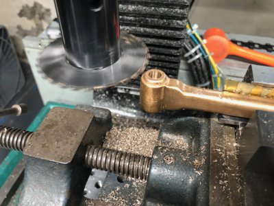
At this point, I had faced both the top and bottom sides (dimension within 0.0010" of nominal) and the slot width (within 0.001" of nominal). Unfortunately the 3" saw was too small to give the full slot depth required.
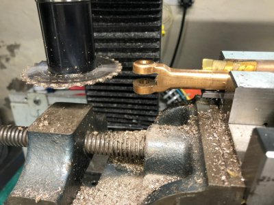
I revisited the cut with a 4" diameter 1/16" thick slitting saw. Taking many passes in the Z direction, each less than the blade width, I was able to mill the slot to full depth, with a flat bottom. The finish was actually perfect, and you can't tell I worked at it through many passes.
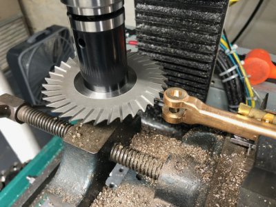
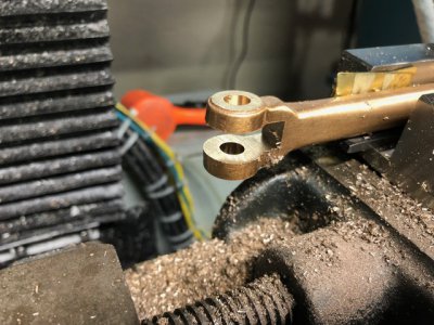
Here I checked the fit to the cross head. The fit is very nice, albeit just a smidge tight. The crosshead bearing faces that rub on the inside of the connecting rod were machined slightly out of parallel previously. The fit is still very buttery smooth and will likely loosen up just a bit as things wear in.
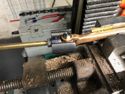
All in all, this took 8 hours yesterday, and a total of 13.5 hours including the scrap part.


