Mike's P.M. Research No. 6 Steam Engine

macardoso

H-M Supporter - Silver Member
Joined
Mar 26, 2018
Messages
2,724
Hi All,

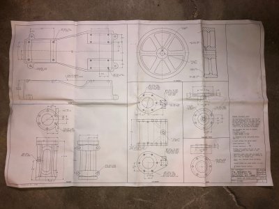
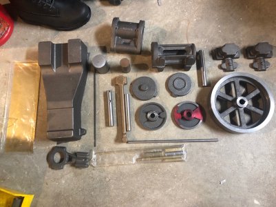
Buddy of mine at work approached me to see if I could help him complete a P.M. Research No. 6 Steam Engine kit that he bought 10 years ago. He used to work as a high school shop teacher and had access to machine tools, however not long after he bought the kit, he was laid off. He had only done a couple of the parts and had probably 95% of the work left to do. Now I get to have all the fun machining the parts, and he gets to keep the finished steam engine. I've been looking for a project so this will be perfect.

Engine Specs:
  • Bore 1-1/2”
  • Stroke 2-1/2”
  • Double Acting
  • Height: 7-1/2″
  • Length: 18″
  • Width: 8″
  • Flywheel Dia: 6-7/8″
  • Rating: 1/4 HP

I wanted to start this post to document my progress and ask questions when I get stuck.
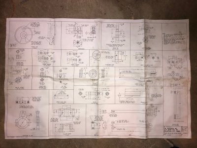
image031.jpg

image030.jpg

image033.jpg
 
Last edited:
I opted to start with an easier part to get started on this project. I used some stock I had on hard since I hadn't yet gotten the stock from my friend.

image027.jpg

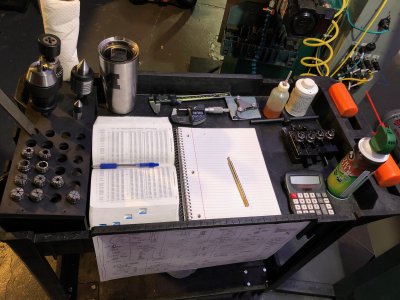
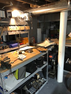
I have a '94 Enco 12x36 Belt Drive lathe and a G0704 converted CNC mill which I'll be using for these parts. I always clean my benches before I start working. I have a rolling cart that makes a great mobile work station to set up near the lathe or mill.

image026.jpg

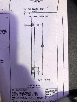
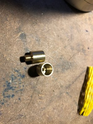
I started from 3/8" brass stock, first turning the thread diameter and single pointing the 5/16-18 thread. I opted for a 2A thread class.

image025.jpg

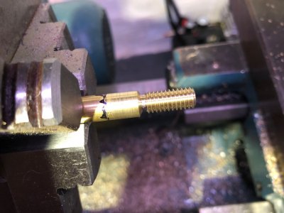
The first attempt ended in sadness when I accidentally split the 1/4-28 thread. I am threading in a captive segment and then parting off, so I don't have any time to remedy a bad engagement of the threading lever. I was going to press on a new piece of brass (That's why it has been turned down to a stud) and try again, but I opted to just start over.

image024.jpg

The single pointed thread (while accurate) had a very poor finish. My lathe had never single pointed nicely without really bad chatter on the flank of the thread. It can take some really heavy cuts normally, so it has something to do with the leadscrew/halfnuts.

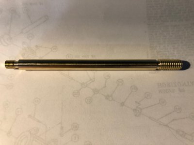
The second attempt I single pointed to half depth and finished with a split die. This gave a great finish and the thread over wires was 0.0002" over the center of the tolerance - nice!

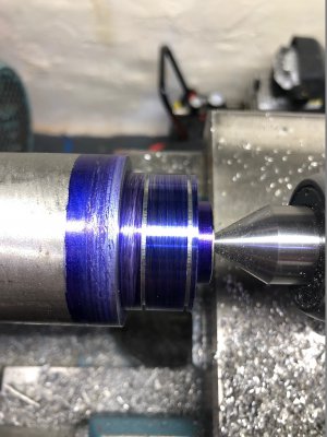
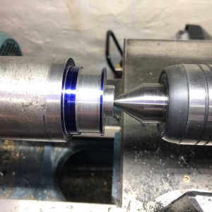
image023.jpg

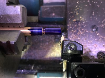
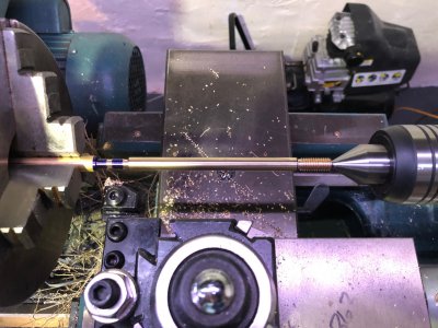
Bar was extended and a live center used. The second thread will be cut captive again in the area painted black.

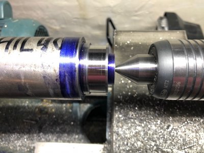
image021.jpg

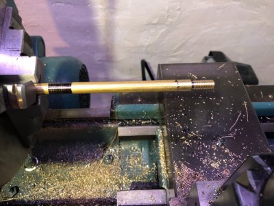
Thread diameter cut, about to start threading the 1/4-28. This went perfectly this time and mic'd over wires at .0004" over the center of the 2A tolerance. After the threading was done I finished the bar to 0.3125 and got within 0.001" over the entire length.

image032.jpg

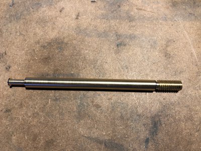
This finish is as-machined using CCGX inserts. Super happy with it.

image020.jpg
 
Last edited:
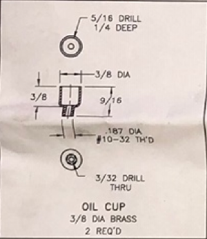
Next I made 2 Oil cups from the same 3/8" brass bar.

Oil Cup.PNG

I don't have pictures of it, but the 10-32 thread was first cut with a die and the blank parted off. I then faced, drilled, and tapped the end of the barstock to make a fixture for the second operation.

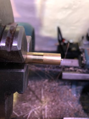
The oil cup was threaded onto the bar, faced to length, drilled, reamed, chamfered, and finally lightly polished.

image019.jpg

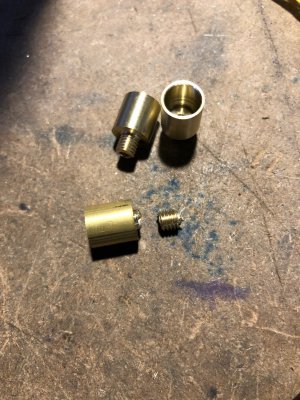
Here are the two completed oil cups. They were super easy to make so I may revisit them later to add an aesthetic radius on the sharp edge.

image018.jpg

I did scrap one attempt when I accidentally jammed the large drill into the part when moving the tailstock in. It bit into the part and snapped the thread off inside the fixture. I removed it using a #4-40 LH tap.

image017.jpg

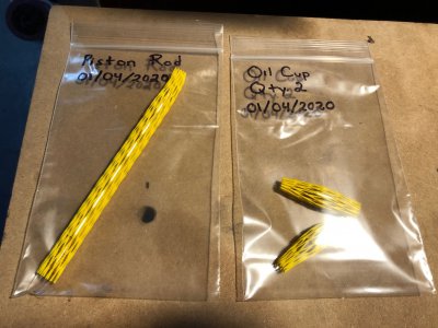
I am cleaning the parts, packing them in protective tubing, and bagging them up.

image016.jpg

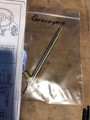
I've also started a collection of all the scrap that I'm making :rolleyes:
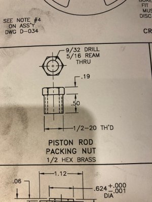
image015.jpg

Not worth writing home about, but I made a simple brass pin which will be hand fitted during assembly of the engine.

image014.jpg
 
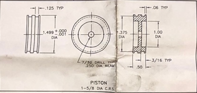
Next I started on the piston which requires moderate precision. The kit provides you with a small chunk of 1018 CRS, but I opted to cut it from a larger bar of 41L40. This made fixturing a bit easier too.

1578591852691.png

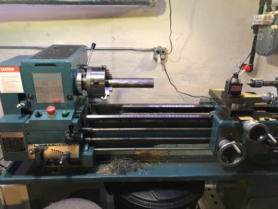
Here's my lathe with the 41L40 bar.

image013.jpg

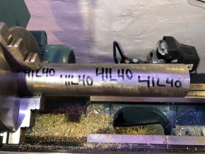
I mark all my material like this to prevent a bucket of "Mystery metal".

image012.jpg

I don't have pictures from the first operation, but the OD turning was done with a CCMT fine finishing insert to a diameter of 1.4986. I'm pretty sure it is down to 1.4985 now after a bit of polishing.

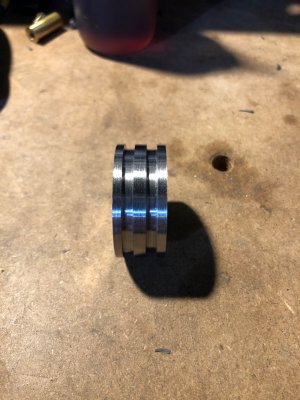
The grooves were cut with a 0.059" Groove N' Turn insert from Kaiser tool (promo picture below). The inserts are $15 and the tool was $110 (purchased for a paid job), but you can't beat them for quality and performance. I plunged straight into the part and then just fed over to cut the groove. Right on size!

1578591824811.png

Here is the part after parting. Finish looks better in person (as it always does).

image011.jpg

image010.jpg

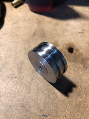
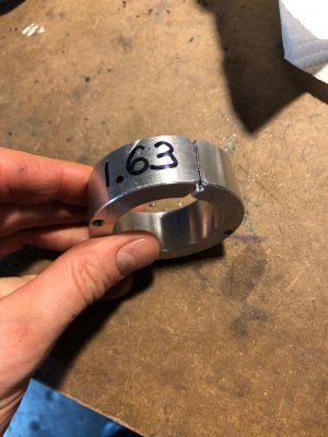
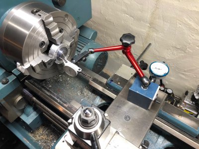
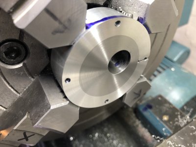
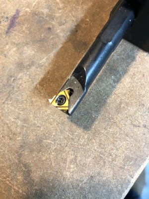
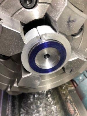
For the second and 3rd operation, I bored and split an aluminum ring. The part was dialed in for axial and radial runout using my Interapid 0.0001" dial test indicator. I called it good enough when I got to about 0.0003" TIR. The trepanning was cut using a brazed carbide boring bar since I didn't have an indexable one this small. The center hole is reamed 0.2500". This operation is repeated on the other side.

image005.jpg

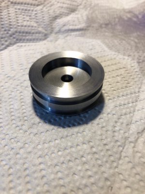
All done! Finish is excellent. My lathe imparts a visual swirl pattern when facing (visible in photo). It certainly can't be felt but I'd love to know why that happens.

image001.jpg

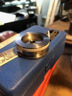
Here is a test fit with the teflon sealing rings. They are a firm but really nice fit into the grooves.

image002.jpg
 
Thanks for posting your (his) project.
Built a PM No 1 a few years ago, was a fun project.
Ran across a set of castings for a Stuart No 4 about a year ago. That turned into an addictive project, couldn't leave it alone.

Greg
 
That's where I'm at right now. If I really love this once I'm done, I may have to get one for myself. Honestly the idea of not keeping the finished product doesn't really bother me so far.

I can see there is a lot of work that will go into this. I've never started machining a raw casting that didn't have some kind of precision surface, so that will be an adventure. Probably going to be asking for advice on that.
 
Love it, keep the updates coming!
 
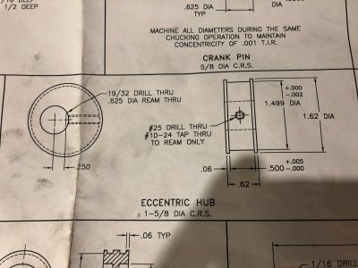
Finished The Eccentric Hub, a part that turned out to be kinda tricky!

image046.jpg

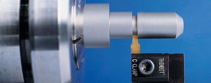
To start, I turned down the barstock of 41L40 do the lip diameter of 1.62". Using my Thinbit grooving tool, I cut the edges of the journal to almost full depth. The first attempt to traverse the groove resulted in breaking the insert ($15 ouch!) and scrapping the part. On the second attempt, I tried using my threading tool to turn the groove and it worked beautifully!

image007.jpg

I got the diameter and width within 0.001 and came back with the Thinbit tool to finish the journal floor and walls to size. Journal was 1.4981" and slot width was .502". I'm really happy with that!

image009.jpg

The journal was polished with extra fine scotch brite before parting the piece off. The is about 0.0002" of concavity across the journal, probably from polishing. I left a nub of material near the tailstock to help me indicate the part in later.

image006.jpg

I made another split ring to hold this part in the 4 Jaw chuck.

image035.jpg

Kate felt like hanging out and watching me work. Not sure why she picks the ice cold surface plate as a cozy place to lay down?

image039.jpg

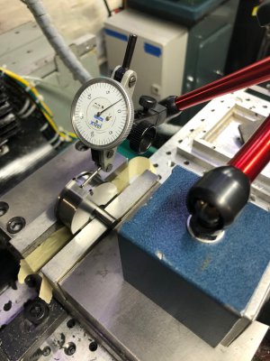
To dial in the eccentricity, I first got the part running true both radially and axially within a tenth or two. Then I zeroed the test indicator and backed the cross slide away by 0.250" (verified by the dial indicator). Then I adjusted the jaws of the chuck to throw the part out of center. As I got close, I would rotate the chuck to find the high spot using the DTI, once that read zero, I knew the part was correctly aligned for the eccentric throw. My only gripe is that I had no way to re-verify the axial runout after I dialed in the eccentricity. If I were to do it again, I would leave a much larger diameter nub to indicate on. I think I ended up with about 0.001" of axial runout of the shaft bore to the journal. Would have preferred this to be much less.

image042.jpg

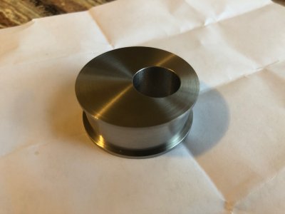
The part was faced to final size, and the through hole drilled and bored to a snug sliding fit on a 5/8" shaft. I don't trust reamers to get me on size, so I opted to do it with a boring bar. I think my tailstock needs alignment. The two tone of the steel on aluminum is pretty neat.

image059.jpg

The part was flipped in the split ring, indicated for zero axial runout, and faced to final size.

image062.jpg

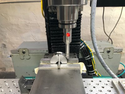
For the final operation (the threaded cross hole), I put the part in the jaws of my mill vise and used a pin and indicator to clock the part so the cross hole was exactly aligned across from the throw of the eccentric. Basically I'd rotate it a tiny bit, find the high spot with the indicator, then rotate it a bit more. Eventually I'd find the maximum high spot which would occur when the cam was perfectly vertical.

image067.jpg

The part was centered up using a electronic edge finder. The cylindrical ball allows you to center on symmetrical 3D surfaces which is really handy.

image068.jpg

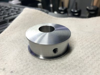
The hole was drilled and tapped 10-24. I was really scared of breaking the tap, but it ended up fine!

image072.jpg

4 setups and 8 hours of work went into this part, but it is very accurate and well within tolerance. I sprayed it down with rust preventative and bagged it up!

-Mike
 
Excellent!! Please continue updates with your progress. I am interested in building steam engines this summer. I will be following how you do different steps and the results. Charles
 
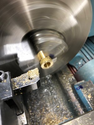
Finished up one of the packing nuts that I started over the weekend. This part was fairly simple and was a good change to practice some more single pointing.

image080.jpg

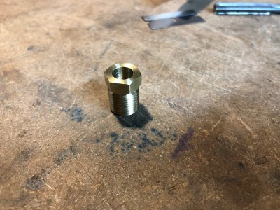
Didn't get any pictures of the threading, but I basically cut a relief groove behind the thread and took many passes while checking for final dimension within a 2A thread class. Hit it right in the middle. The center bore was reamed, but I got a really garbage finish. Not sure why...

image075.jpg

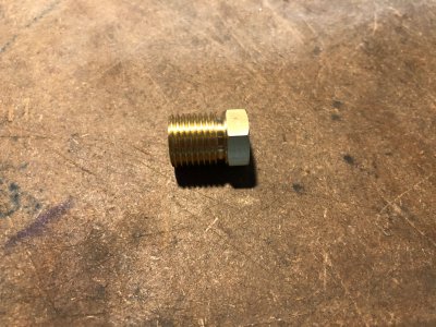
The hex was finished to dimension and gently polished.

image076.jpg

image077.jpg

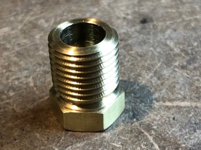
In this closeup, you can clearly see the chatter marks on the threads. The tool cuts cleanly, the thread assembles fine, but it just looks weird. I haven't been able to pinpoint why it happens or how to fix it. The tool cuts without those mark when it is used without the leadscrew, but has those marks while threading.

Center bore is on size, but the finish is pretty poor.

image079.jpg

I used this LH ID threading bar to chamfer the front and back corners of the hex.

image081.jpg
 
Back
Top