Mike's P.M. Research No. 6 Steam Engine

Ugh :) No, I have this on the back burner. Wife warned me that starting a second project at the same time was not going to work. I bought an industrial robot back in May and have been working to get it running again. It is a blast, but have not gotten much machining done otherwise.


I am through most of the larger components and the stuff that is left does not look too bad to do. I think the next step is finishing the cylinder casting by drilling and tapping all of the little holes that mount components.
 
Well @Manual Mac, you got my interest going on this project again! I normally only write a post when I finish a part, but I've been so slow at this I might as well catch up on where things are.

Previously, I did a lot of work on the main cylinder. It is nearly done with the exception of the mounting bolt circles. I need to do these but I'm a bit nervous to do it since I already have so much time invested in it.

This is the cylinder casting. It requires two faces, two precision spaced and sized bores, bolt circle holes tapped on two sides, steam port hole cross drilled and tapped, and insulation plate mounting holes drilled on the periphery. The #5-40 tap is going to be a bit tricky to find.

image055.jpg

image034.jpg

The first operation was to dial the part in using the 4 jaw to center the large bore and align the angle of the part. This is the most time consuming part I have found when working with castings. This flat face becomes the part datum.

image035.jpg

Once a datum face was established, the part was bored to a precision fit to the piston. This was done using a 3/4" steel indexable boring bar.

image037.jpg

Here is the air tight fit. The piston slides easily on a thin film of oil inside the bore, but is pretty tight once the teflon packing is added. I think I need thinner teflon.

image038.jpg

Here is the bore finish. I have a bore hone which will be used to lightly cross hatch the surface for better oil bearing. The rough slot on the left is a steam port in the casting.

image045.jpg

As mentioned earlier in the forum, I was having a really hard time figuring out how to cut the valve cylinder, which runs parallel to this bore. It is .625" diameter hole, 4 inches long and must be an air tight sliding fit to the steam valve with a light coat of oil. I ended up buying an undersized reamer 0.624 and machining the end to fit my drill chuck. Thanks to @bakrch, I had some 440C stainless to practice machining on and was able to get the fit and finish I needed. The second bore was again painstakingly aligned using a tenths indicator to be centered on the casting, parallel to the main bore to 0.0005"/4" and within the published center to center distance within 0.0007"

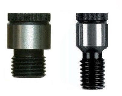
Here is the reamer with the reduced shank. Surprisingly to me, the shank is very soft steel.

image048.jpg

Practice bore in 440C Stainless.

image049.jpg

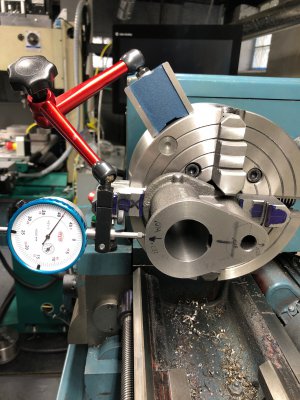
Offset chuck boring operation.

image051.jpg

Here I was measuring the throw of the chuck as I adjusted it. Timing marks were scribed into the chuck jaws and the part to make sure it did not rotate in the chuck during adjsutments.

image057-jpg.350116


Once I was confident in the setup (center to center measured as 1.9997"), I drilled, bored, and reamed the hole to finish size.

image059.jpg

image061.jpg

And here is the final fit of the steam valve. If the valve didn't have a chamfer, you likely wouldn't be able to see the edge between the two parts. The valve slides in the bore with little friction once lightly oiled. Honing this cylinder would be nice, but I don't have a tool to do it.

image063.jpg

This is where the cylinder sits today. I need to drill the bolt circle holes and tap them and do the steam valve drill and thread. After the bolt circle debacle on the frame, I am a bit nervous to do this one.

More to come
 

Attachments

  • image057.jpg
    image057.jpg
    650.4 KB · Views: 131
Last edited:
Started two days ago on what I thought would be an easy part to ease back into this project, but I am concerned I might have picked one of the hardest!

Enter the crosshead!

image082.jpg

In this steam engine the crosshead (#12) rides inside the "frame" (#2) to support the piston inside the cylinder. It is linked to the piston using the piston rod (#19) traveling through the inboard head (#3) and the packing nut (#45). The cross head cycles down the length of the frame with every stroke of the piston and serves as the pivot and attachment point for the connecting rod (#11). It has oil passages to collect oil from the oil cup (#44) and disperse it to the sliding surfaces and the pivot bore.

image083.jpg

The crosshead comes as one casting, connected to the eccentric arm. These are separated with a hacksaw and substantial bench work was done to clean up the flash.

image065.jpg

The part was indicated true on the lathe and the back surface was faced and the internal holes drilled and tapped. I also added my first "apprentice mark" to the lathe jaws :bawling: . I was trying to turn the OD and snuck the tool into the bevel near the tips of the jaws. What I didn't see or account for was the other jaws being closer to center and not having the clearance of the bevel at the tip. I am really mad at myself, but it isn't the end of the world. Maybe I can find a set of replacement jaws.

So anyways this part is tricky because it has a number of precision features but nothing to reference. This face and the axis of the pitch diameter of the thread become the datum for all subsequent measurements. I turned down part of the OD to a non-finish diameter to allow me to verify the part is running concentrically in future operations.

image068.jpg

OD finishing will be done on this fixture which has been drilled, faced and tapped in-situ to guarantee best accuracy. a 5/16 bolt was loctited in place and faced off to become a mounting stud.

image070.jpg

Before finishing the OD, the connecting rod pivot bore and spot faces should be machined. A 3/8" shoulder bolt with a 5/16" thread is tightly installed in the thread and seated against the face. This allows me to accurately indicate the part for angular alignment in the Y and Z axes as well as determine the X, Y, and Z coordinates of the datum. Roll (rotation about the X axis) is not important in this setup and is set by standing the rough cast surface on parallels. My Interapid 0.0001" DTI was used to align everything within 0.0002" over 2"

A CMM thread locator would have been more accurate, but the shoulder bolt should do. In addition, these CMM locators are crazy expensive!


image072.jpg

An electronic edge finder was then used to locate the center axis of the shoulder bolt and the datum face.

image073.jpg

The reamed hole was predrilled to 95%.

image074.jpg

Due to tool holding inaccuracies, the reamer initially had 0.0030" of runout. 20 minutes of careful indicator work and tapping with a lead weight centered the reamer within 0.0003" TIR. John Saunders of NYCCNC taught me this trick!

image075.jpg

I didn't have a tool to cut the 7/8" diameter spotface, so I wrote a quick CNC program to mill the pocket with a 1/4" endmill.

image078.jpg

And here is where I got to. This whole process needs to be repeated on the second side with the addition of carefully indicating the part in roll to make sure the spotface on the second side is parallel to the first. Then the 2 cross drilled oil holes need to be added, and finally the part can be OD turned for a precision running fit to the frame.

image080.jpg
 
I’m really enjoying your build, thanks for bringing us along.
Thanks for giving me a kick in the you know what to get started again! Will be switching back and forth between this and programming the robot in the coming weeks/months.
 
Finished the cross head!

The alignment of the second spot face to the first was very tricky and ended up not being perfect. Some of my techniques worked great while others did not. The first thing to do was align the part rotationally in the vise in all 3 axes. The roll of the part along the X axis was controlled by placing a gage block against the freshly machined surface.

image085.jpg

The pitch and yaw about the Y and Z axes were controlled with a cradle I built which pushed against the shoulder bolt. I could indicate the top and sides of the shoulder bolt using my tenths indicator and adjust the screws pressing against the shoulder bolt to align the part. All in all, I got these within 0.0002"/2".

image087.jpg

image088.jpg

XY center was indicated off the reamed connecting rod pin bore and Z was taken off the top of the center of the shoulder bolt.

The CNC program was run again, first at half depth to measure the web thickness and again a full depth adjusting for error in Z positioning

image090.jpg

All said and done, the web thickness measured 0.3751" in the center (nice!) and had 0.0001" of taper front to back, but a really bad 0.0100" of taper side to side. The part ended up not wanting to sit flat on the gage block and was rolled along X for the final machining. This shouldn't cause problems in operation but I was bummed about it. If I were to do it again, I could have indicated the walls of the bore along the Z axis with my DTI and I would have seen the bore was slightly crooked.

image092.jpg

Oil holes were drilled through the part after setting it up similarly to before using a 3/32 drill.

image094.jpg

The final feature is a hole at a 60 degree angle from the side which vents air to allow the oil to flow. The part was held in a small Sherline tool makers vise with a 30 60 90 block underneath to set the angle.

image100.jpg

The dowel pin in this setup is critical to ensure the rough cast surface it is resting against did not twist the part in the vise. The part center was edge found from the machined OD and the X position was aligned visually from a scribe line on the part

image101.jpg

Drill depth was determined by some basic math off the various features and trig to account for the angle. Would have been easier to just listen for the drill to break through to the center.

image105.jpg

The part was mounted on the lathe fixture and indicated true to the previously machined OD and spot faces. OD turning was very quick using a CCGX insert to give the final finishing passes. OD was machined to 1.4990" and the bore of the frame is 1.4998". The fit is so perfect and a light film of way oil allows the parts to slide silently over each other. I bet the fit will loosen as the parts wear in initially and the prominences are rubbed down.

image106.jpg

image110.jpg
 
Felt like taking stock of where I am at currently. Here is a picture of a real life exploded parts diagram of the engine (minus screws and missing parts).

image113.jpg

Here is a list of machined parts and my status:

Crank Disc (Qty. 2): Partially machined by my buddy, incomplete
Cross Head: Done (8.5 hours)
Crank Pin: Incomplete
Lower Valve Head: Done (2 hours)
Piston Rod Packing Nut: Done (1.5 Hours)
Lower Linkage: Done (2.25 Hours)
Upper Linkage: Done (2.25 Hours)
Eccentric Hub: Done (8 Hours, 1 Scrap)
Wrist Pin Bolt and Nut: Done (1 Hour)
Valve Head: Incomplete: Incomplete (1.25 Hours, 1 Scrapped)
Valve Rod Packing Nut: Done (1 Hour, 1 Scrap)
Oil Cup (Qty. 2): Done (1.75 Hours, 1 Scrap)
Piston: Done (5 Hours)
Lower Valve Rod: Done pending final fit (0.5 Hours)
Pillow Block Cap (Qty. 2): Incomplete
Eccentric and Cap: Incomplete
Upper Valve Rod: Done pending final fit (0.5 Hours)
Valve: Done (3 Hours)
Crankshaft - Short: Done (0.75 Hours)
Crankshaft - Long: Done (0.75 Hours)
Piston Rod: Done (4.5 Hours, 1 Scrap)
Pillow Block (Qty. 2): Incomplete
Rod and Rod Cap: Incomplete (0.5 hours)
Base: Done (5.5 Hours)
Flywheel: Done (1 Hour) Buddy did this one, I just skimmed it true.
Frame: Done pending drip oiler selection (10 Hours including repair)
Cylinder: In Process, mounting holes needed (5.75 Hours)
Inboard Head: Done (3.5 Hours)
Head: Done (1.5 Hours)

Recorded hours to date: 72.25 Hours
(probably close to 90 including cleaning, bench work, and planning)
Estimated Completion: 60%

And some close ups:

This is the cylinder detail. The piston is sandwiched between the two heads and connects to the crosshead with the piston rod (far right)

image114.jpg

Here you can see all the details of the valve linkage.

image115.jpg

Here is the crosshead, connecting rod, and frame.

image116.jpg

Here are the crankshaft components. This is the most incomplete section of the engine.

image117.jpg

Base and flywheel.

image118.jpg

Raw stock plus bronze bearings not in the kit for the bearing blocks.

image119.jpg

I want to focus on the components needed to start assembling this up on the base. Finishing the cylinder and getting the bearings done will be the next things for me to focus on.

To be continued...
 
Finished the crank pin last night.

The part started from 12L14 centerless ground barstock.

Since the OD of the part is the nominal dimension of the stock, it had to be indicated in very carefully.

image120.jpg

I then skimmed the entire surface to clean up. OD of the part ended up 0.6235", well within tolerance.

image121.jpg

The first press fit stub was turned to 0.3765" on a target dimension of 0.376" +0.0005 -0.0000.

image123.jpg

To maximize concentricity, all features (other than remove the parting nub) were completed in one setup. I have a LH VCMT insert tool which allows me to do this kind of work. I utilized the DRO Sub-Datum Memory (SDM) as tool offsets to switch between the LH and RH tools.

image124.jpg

I used plunge roughing to start the cut in the middle of the workpiece. I turned the collar to 0.118" on a 0.120" +0.000 -0.002 calculated tolerance. For some reason, my ability to accurately turn dimensions in the Z axis are limited to about 0.001-0.002 while my ability to hold diameter tolerances if I try is 0.0001-0.0002".

The critical running diameter of the pin was finished on the right half to 0.4986" on a 0.499 +0.000 -0.001 tolerance.

image126.jpg

I then finished the left side of the groove with the RH tool to the exact same 0.4986" as the right half. There is absolutely zero blend line between the two. Also the phone camera makes the surface finish look way worse than in real life which is weird.

I turned the other press fit stub the same way I did the center groove, hitting 0.3765". There is a call for a press fit lead of 0.002" off the diameter over 0.060" on each press fit stub. Doing some trig calculates a 0.955 degree angle. This was dialed in on the compound (rounding to 1.0 degrees) and the length of the taper was determined against a scribe line visually. Both sides were cut at the same time.

I started the parting operation, but waited to go to full depth so I could chamfer the back corner.

A light 45 degree chamfer was made on all corners and finished the parting off.

image128.jpg

Finally the part was rechucked in a crush ring fixture, reamed to 0.6240. The part was brought close to true and the parting nub was machined flush to the face.

image129.jpg

Here is the final part.

image132.jpg

Total time was 2 hours.

As an aside, I don't know how I lived without my Interapid tenths indicator before. It has enabled me to do so much more accurate work.

I think my biggest limit to accuracy is my chuck. While I can dial in the runout to 0.0001", there is a parallelism issue somewhere and the part will sit crooked by about 0.0001-2" over 2". Doesn't seem like much but it is the limit on my work holding accuracy.
 
To maximize concentricity, all features (other than remove the parting nub) were completed in one setup. I have a LH VCMT insert tool which allows me to do this kind of work. I utilized the DRO Sub-Datum Memory (SDM) as tool offsets to switch between the LH and RH tools.
Nice work as usual; space shuttle attention to details. I'm going to have to read my DRO manual for the sub-datums; great idea on the tool positions. Pretty sure mine is one of the Chinese-generics with 200 sub-datums.

Bruce
 
Back
Top