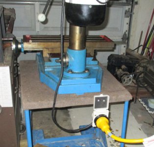
Mill spindle comes to speed, click, slows down, click, repeat

thanks J - I'll mention the planer at bottom...


update on the mill:


bad start cap for one thing...
...but was it ever good being run on 110v even when it “worked”?

So:
The motor capacitors are:

CD60, 220/265 V.A.C., 150 MFD
(presumably the START cap)
*THIS one tests BAD (meter says 0.F)

- - - -

CBB60 SH, 450 V.A.C., 25 MFD
(presumably the RUN cap)
This tests 23.88 MFD on the outside of within +/- 5% tolerance

* So it's staring to look like the theory of it not having enough oompf and getting to speed?

Question: If it's not getting to speed (and it does seem sluggish starting) then I presume the <click> is not the centrifugal switch successfully tripping but rather, what (?) a thermal breaker (like it sounds) tripping because startup is straining and/or taking too long and causing too much heat?

I still wonder if I should try 220v...but 220v single phase (even though ads for this motor say it's a three phase motor?
It seems like the point of this present arrangement is single phase, right?

I do have single phase available more readily than three at this location (allow electrician to tap in near the water heater instead of near the drier) and I'd have to get help with wiring. I say “single phase” when I really perceive “220v single phase”as two phase, but anyway...

I'm a hack in this area and appreciate the help immensely!

P.S. -- reply to user: Just for Fun in Washington -- thanks for the reply -- Well, the only reason I mentioned the planer was as a reference (as in "If a motor is made to work on either, will it say so?"). I noted the A-OK planer's manufacturer's plate said 220v or 110v, whereas the problem mill's plate says just 220v making me wonder if it wasn't meant for 110v no matter how you wire it. Like maybe it requires inordinate current for a typical 15 amp circuit or something. Maybe you meant look at it to see if the mill is wired the same? That might have helped me learn but I do think the planer is a 1-cap deal. I DO wonder if maybe the guy that had the mill might have done was you say and used a 110v plug and outlet to run 220! I wouldn't bet my life against it! Haha...
 
Certainly you need a new start cap, but it's still not certain what voltage it's wired for. Personally, I would study the wires coming out of the motor and try to identify the two run windings and if they are connected in series or parallel. Series means 220, parallel 110. If it looks like only one run winding then the motor is a 220 volt only motor for sure.
It looks like there are six wires coming out so that seems to indicate 2 run windings and one start winding. Need a close-up view though.
 
Can't thank you enough...
(ordered new caps)
Just ignore this if it seems like a mess but I thought it might help...

I'm truly dyslexic so I'm still working on a schematic for this as we speak, but it appears to me as if:

There are only 3 wire colors associated with the motor,
but two groups of the same three colors:

-- two holes in the motor next to each other
-- each hole with its own group of White, Yellow, and Red
(then there are thinner wires below that come in from the power switch and power source in blue, red, and striped yellow/green grounded to chassis)

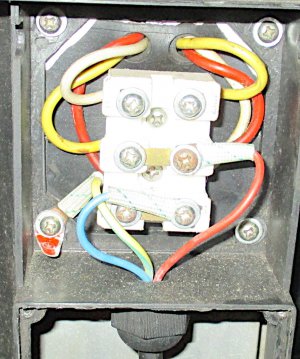
Here I have removed the capacitors...
NOTE: the only wire that looks deceiving is the White motor wire on the Right side goes into the Bottom Right Post (not the Middle Right Post with the Red one like it looks, sorry)
but I do label and describe further down

wiring1.JPG

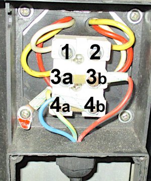
here I label with numbers so I can explain where the wires go since I'm struggling with a real schematic quite yet:

wiring2.JPG

The letters are electrically meaningless (shown for position only) because 3a and 3b are linked to each other with a brass band, just as 4a and 4b
- - - - -
* 150 uf capacitor goes to posts 1 and 2

* 25 uf capacitor goes to posts 1 and 3a
- - - - -
I'm going to call the first group of motor wires X
Red X, Yellow X, White X

and the second group of motor wires Z
Red Z, Yellow Z, White Z
- - - - -

White X wire ---> post 1
Yellow X wire ---> post 3a
Red X wire ---> post 4a
- - - - -

White Z wire ---> post 4b (NOT 3b like it looks, sorry)
Yellow Z wire ---> post 2
Red Z wire ---> post 3b
- - - - -

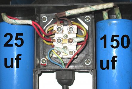
Here's a pic with the caps in place
wiring3.JPG

Actually it's easier to see wire White Z going to post 4b in this picture

Thanks again and I know the above is bulky and inefficient representation... thanks for bearing with me.
 
Last edited:
Can't thank you enough...
(ordered new caps)
Just ignore this if it seems like a mess but I thought it might help...

I'm truly dyslexic so I'm still working on a schematic for this as we speak, but it appears to me as if:

There are only 3 wire colors associated with the motor,
but two groups of the same three colors:

-- two holes in the motor next to each other
-- each hole with its own group of White, Yellow, and Red
(then there are thinner wires below that come in from the power switch and power source in blue, red, and striped yellow/green grounded to chassis)

Here I have removed the capacitors...
NOTE: the only wire that looks deceiving is the White motor wire on the Right side goes into the Bottom Right Post (not the Middle Right Post with the Red one like it looks, sorry)
but I do label and describe further down

View attachment 344279

here I label with numbers so I can explain where the wires go since I'm struggling with a real schematic quite yet:

View attachment 344280

The letters are electrically meaningless (shown for position only) because 3a and 3b are linked to each other with a brass band, just as 4a and 4b
- - - - -
* 150 uf capacitor goes to posts 1 and 2

* 25 uf capacitor goes to posts 1 and 3a
- - - - -
I'm going to call the first group of motor wires X
Red X, Yellow X, White X

and the second group of motor wires Z
Red Z, Yellow Z, White Z
- - - - -

White X wire ---> post 1
Yellow X wire ---> post 3a
Red X wire ---> post 4a
- - - - -

White Z wire ---> post 4b (NOT 3b like it looks, sorry)
Yellow Z wire ---> post 2
Red Z wire ---> post 3b
- - - - -

Here's a pic with the caps in place
View attachment 344281

Actually it's easier to see wire White Z going to post 4b in this picture

Thanks again and I know the above is bulky and inefficient representation... thanks for bearing with me.
This is not the first time wiring issues have been been brought up. Each one seems to be different, also.....
 
Sigh...
Well, another update (please note I have depicted wiring more clearly above it that helps Markba633csi or anyone mire, thanks)

It turns out the 150uF capacitor I thought tested bad is probably fine anyway.
I got the new one (with also a new 25 uF on the way) and it also made my meter say "0.F" :(
I thought that meant that it was bad since it reads the 25uF capacitor just fine (and is supposed to auto range).
But I dredged another tester out tha, now, indicates all the caps are OK.

So I tried it anyway and pretty much the same result.
Probably will be the same when the 25uF cap arrives, too.
I fancy it stayed running longer and had reached top speed briefly but <click> slows down almost to a stop <click> starts again...

I feel like I should just jam 220v into it and see what happens.
But I should learn more about the circuit and know what I'm doing better.
If I was more of an electrical buff I could have already used what HMAN and Markba said about the windings etc., as a point of departure, and determined if it's improperly being fed 110v and just needs 220v.

I'm going to draw the wiring on paper like a cave man schematic for myself to understand it better.

I might change the belt position to lower speed for now. It's on top spindle speed. Wonder what will happen on a lower spindle speed. It should be easier for the motor to hit its same, full motor arbor speed faster with less difficulty or load...? Might help indicate what's going on, by what happens with the belt and pulleys set for low spindle speed.
 
Last edited:
So from everything said I'm installing 220v in the garage tonight.
I found I already had actual 220v connectors and big yellow cable and everything from a late buddy.

NOTE: I WILL NOT hold anyone responsible (if the motor fries) for giving me their best guess of if I should change the wiring before trying 220v.
The motor is starting to look expendable since it has no diagrams available. It would save time and tight money if saved.

Whether we can salvage this motor or I must consider the $170 replacement I have my eye on, I'll run 220v either way.
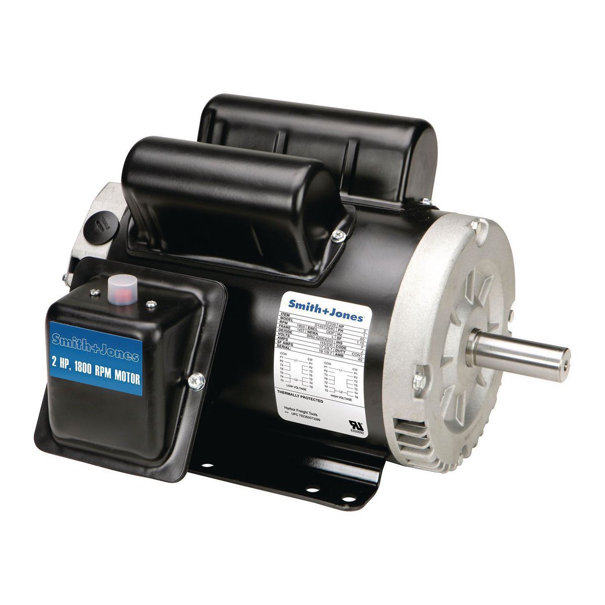
This one below appears to have the right 7/8 shaft (I THINK the pulleys are 7/8" with 3/16" key slot, but measuring assembled is hard... those are the specs unless they're metric and very close)... could the stock motor shaft be metric? I'll disassemble and measure before paying for a motor...
(I like that I could pick this up same day... I'm behind on my work at home manufacturing plan I'm financially dependent upon, hehe, so I can't wait around.

5:00AM -- "time to machine the wooden flutes" (instead of "make the donuts").

* I just need to figure out if I need to change the wiring on this old motor before trying powering it up with 220v.

* While it sounds to experts here maybe it was never converted to 110v on one hand, on the other hand my friend showed me parts he machined with 110v before this problem became intermittent then permanent.
Could he be dishonest despite encouraging me to let him fix it before buying? (I couldn't wait or risk losing it)
Or could a 220v-only setup, wired that way and everything, have actually gotten up to speed and operated (somewhat) for a while, when in better shape, with half the voltage it was supposed to get (until it got abused overheating and now suffers too much to do so)?

* Weird thing is -- it seriously looks like it came with this 110v plug on it from the factory, despite the 220v spec plate. There's no retrofit evident and the power cable goes into the machine deeper into the cast iron machine (to the switch) than I'd have thought these guys would go to the trouble of disassembling just to swap a plug.

I'm off to try crawling thru the attic to run 220v with a freshly hurt back...

As always THANK you
 
Last edited:
I don't have any useful insights, though I am watching this with some interest. Since I can't help you, I thought I'd entertain you.

When I ran the new circuit for my shop, I told the electrical supply I wanted the biggest, baddest breaker I could run on 110. Now that I think about it, what the heck did I actually end up with? (Looks at panel.) It's a 30A single pole breaker that's fat enough to take up two slots. How does that work? Now that I'm thinking about it, I'm not even sure I installed it correctly the second time, but whatever, it's been working for 15 years at this point, and it trips when I do dumb things like try to take off 0.250" in one pass with my lathe. Did I mention the only electrician I've used since I bought this place is kind of a moron?

Anyway, the first time I installed this thing, I didn't appreciate how double pole breakers work. I just installed this fat single pole breaker somewhere convenient, and I spanned both bus bars. I fired up my shop lights to try out my brand new shiny new circuit (my shop was powered with extension cords previously), and lo, DIXITQUE DEUS FIAT LUX, ET FACTA EST LUX!! (Yeah, I'm kind of a dork. Maybe this is why I never get second dates.)

There was also smoke. And a weird humming noise. And more smoke. Lots and lots of acrid, nasty smoke. What the...? So I got out my handy dandy meter, and poked the prongs into a conveniently located outlet. Just before the meter exploded with an earth-shattering kaboom, I saw the number 220 on the screen.

Yeah. I wired the shop with two hots and no neutral. I blew the ballasts out of a dozen shop lights. I'm lucky I didn't electrocute myself, and burn the whole Commonwealth of Virginia to cinders.

So your whole motor clicking and dying thing, hey, that's nothing in the scheme of things. If I were you, I'd roll the dice and plug that sucker up to the 220V without touching the wiring. It will probably work. But we have established that I am a moron, and you probably shouldn't trust my electrical advice! :wink:
 
...DIXITQUE DEUS FIAT LUX, ET FACTA EST LUX!! :wink:
Hehe...
you let there be light
but it was not good

Well... I have beautifully (for me) run 220v, off of my dedicated hot water heater circuit, thru the attic, having created a junction before the heater on/off switch, so I can run the mill with the heater temporarily switched off, since I think maybe it draws about 20 amps out of the available 30 all by itself.

Whatever happens, thanks to everyone for all their time.
Yeah I think it's just time to give it a try. ...but I'm going to shower the fiberglass insulation off my man-boobs first and say a prayer for Deus ex Machina to ...salvum me machina?

I am going to clean her up and name her, but wanted to get her working first

220v-hope.JPG
 
Last edited:
Back
Top