Mill table dual stop

petertha

H-M Supporter - Gold Member
H-M Supporter Gold Member
Joined
Jan 15, 2016
Messages
994
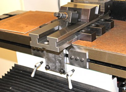
I have a lot internal pocket milling work on the horizon & that can be very tedious chore without some kind of stop to limit travel as you work your way down the material end milling (as opposed to watching dials and/or DRO position at each end of every pass). I made a similar system for my old RF-45 mill & it worked out pretty good. The basic idea is you set the table to desired left position, set the left stop. Then do the same for right. Now when milling you can just traverse the table back & forth until it contacts the stops on either side.

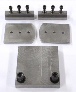
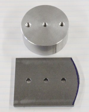
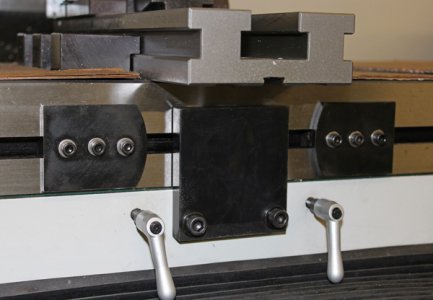
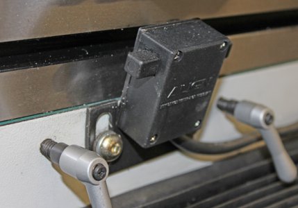
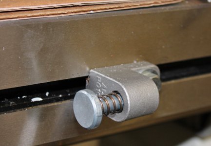
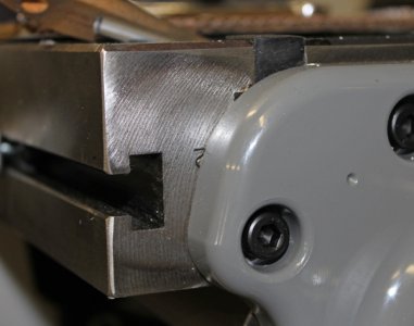
My 935 mill has different dimensions so about all I could use was the concept & materials on hand. I have a power feed on the X so I temporarily removed the limit stop switch, wrapped its cord up neatly & just strapped it to the motor unit so its out of the way. Yes, the electric limit switches work pretty reliably as an e-stop, but I find power feeding short lengths is more of a hassle than its worth. The spring limit bumpers just slide out of the Tee slot along the front of the table. The mill base was already drilled & tapped 5/16 for the center limit switch so I decided to make use of those holes.
 

Attachments

  • IMG_2874_edited-1.jpg
    IMG_2874_edited-1.jpg
    96.7 KB · Views: 32
  • IMG_2875_edited-2.jpg
    IMG_2875_edited-2.jpg
    97.4 KB · Views: 31
  • IMG_2876_edited-1.jpg
    IMG_2876_edited-1.jpg
    95.3 KB · Views: 27
Last edited:
Here are the components. A chunky center stop plate (1/2" steel...cause that's all I had in 3" width), the left & right bumper plates (3/16 steel x 2" high x 2.5" long) and elongated tee nuts to accept them (steel). I made the bumper plates tall to maximize the contact area along the front of the table.

The system cant take a hard traversing hit without losing a couple thou, but I found by just tightening them up reasonably I can easily get half thou repeatability multiple times by just walking the table in slow & kissing the center plate. The three (10-24) cap screws is a bit overkill but A) it spreads the the load & clamps the plate securely just using an hex key on the cap screws B) I make use of this hole layout to make the round-over profile in subsequent step.
 

Attachments

  • IMG_2898_edited-1.jpg
    IMG_2898_edited-1.jpg
    152.3 KB · Views: 27
  • IMG_2899_edited-1.jpg
    IMG_2899_edited-1.jpg
    131.1 KB · Views: 27
Last edited:
Here I'm just using a scrap of aluminum as a turning fixture. The nose radius of the bumper plate can be anything, it just makes tangent contact to the center plate. So by using 2 of the holes & sandwiching the plates together, quick work is made of the curve profile for both parts simultaneously. I hate interrupted cutting because hot chips have a way of finding my head, so I bandsawed most of it away beforehand.
 

Attachments

  • IMG_2889_edited-1.jpg
    IMG_2889_edited-1.jpg
    123.5 KB · Views: 24
  • IMG_2884_edited-1.jpg
    IMG_2884_edited-1.jpg
    73.1 KB · Views: 22
  • IMG_2883_edited-1.jpg
    IMG_2883_edited-1.jpg
    126.5 KB · Views: 22
  • IMG_2890_edited-1.jpg
    IMG_2890_edited-1.jpg
    153.4 KB · Views: 30
Last edited:
Here it is installed. I wish I could think of something similar for the cross axis but its a bit more cumbersome. If you come across any ideas let me know.
 

Attachments

  • IMG_2891_edited-1.jpg
    IMG_2891_edited-1.jpg
    99.9 KB · Views: 30
  • IMG_2894_edited-1.jpg
    IMG_2894_edited-1.jpg
    108.2 KB · Views: 30
  • IMG_2897_edited-1.jpg
    IMG_2897_edited-1.jpg
    134.5 KB · Views: 29
  • IMG_2910_edited-1.jpg
    IMG_2910_edited-1.jpg
    96.2 KB · Views: 30
Good idea.
Very well executed!

Thanks for sharing it.
-brino
 
Back
Top