Millrite MVI spindle bearings replacement

Tim9

H-M Supporter - Sustaining Member
H-M Platinum Supporter
Joined
Oct 11, 2015
Messages
1,196
Here we go again. Another project which totally sidetracked me. I had my mind set to do some anodizing and nickel plating .

Anyway, I was using the mill the other day and noticed that the lower part of spindle was warm after using the mill for a small job. So I decided to disassemble the spindle and clean and reinstall the bearings. At least that was the plan. I was hoping it was just dried grease with still good precision bearing. I had read another thread where that was the outcome of another Millrite. And FWIW, I was hoping all of these things will fix my spindle which isn’t running very true. I believe last time I checked it... it was out of round about 2 thousandths.
After reading numerous threads on this job, I figured I’d need to make a spanner wrench for the lower spindle cap which is left hand threads. From tips in other posts, the trick is to use a threaded stud in a 1/2” collet ... and with a big washer and nut, that holds the spanner wrench in the cap so it doesn’t slip. I don’t think I saw a single post of where the lower nut/cap came out easily.
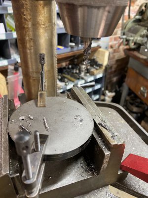
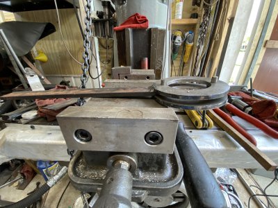
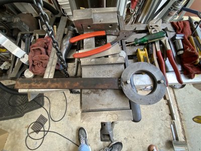
Here’s a couple of pics of the spanner I made. 2 steel plates 1/4” thick with dowel pressed into both plates. The plates are set 1/4” apart with the 1/4 x 1” handle welded between them.
F9697703-3EF1-44C2-B52A-A4B9E9CD7196.jpegA2F0FDE2-FCA8-4CFB-9CD3-D3527625FF8A.jpeg9652B26C-9428-4534-8074-B579804E206F.jpeg
 
Last edited:
I didn’t take pictures of everything, so FWIW, I’ll take a picture of the wrench in use later... once I get everything back together. There are some good posts on a couple of sites which document this repair better than I can do. But, there are even more threads where all of the pictures are now dead due to photoshop and other dead website links. That’s the only reason I decided to post this thread. I’m kind of winging it here, so what I plan on doing is starting this thread and posting the pictures I have. Important missing pictures ...I’ll try to take those as I reassemble everything.
On the lower spindle nut. It’s easier to loosen it while still in the milling machine head because it is held securely there. Much easier loosing this nut here than in a vise on the bench.
After getting the nut loose, I reinstalled it. The trick to loosening this nut is to lower your spindle and lock it with the quill lock. I had to hammer the handle of the spanner wrench while pulling on it clockwise since it’s reversed threads. Without a dedicated spanner held in the nut, forget it. A regular spanner is useless. It slips and messes up the pin holes.
Before the spindle can be removed, the motor has to be moved out of the way. And the spindle pulley needs to be removed. Spindle pulley housing also needs to be removed. There are three screws on it.
Here’s a picture of the motor hanging out of the way. 04123565-214C-405B-A035-3CD03A45F24F.jpeg
 
Here’s the best site with the best instructions I could find. Like I said...many threads on spindle bearings now have instructions with dead photo links.

Mikeamick Millrite page.

and here’s a decent write up of the project on the Burke Mills Groups.io
Groups io Burke Mills Spindle bearings
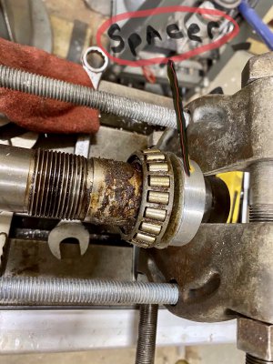
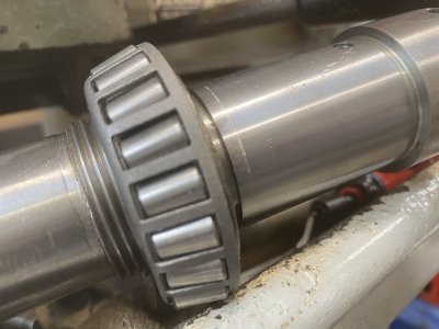
I had to make an aluminum spacer to protect the oil slinger. on a side note....I have the spindle disassembled and found out my bearings are not precision bearings. They are a mix of regular Timken and Bower bearing cups. I ordered new Timken Precision bearings. But it’ll be a few days before I can finish this. I made an aluminum spacer in order to not destroy the oil slinger.
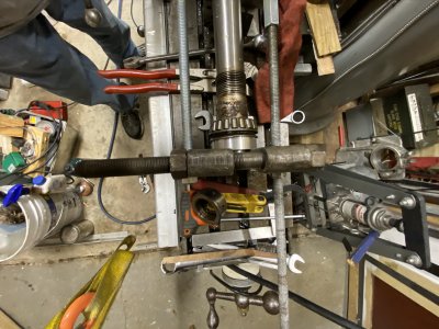
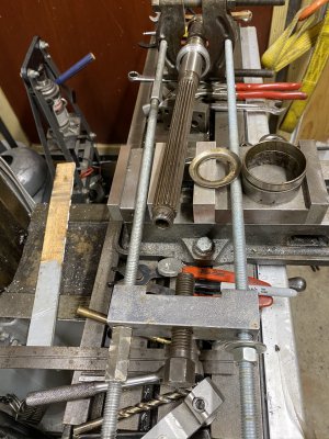
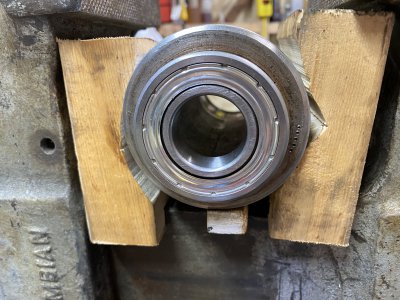
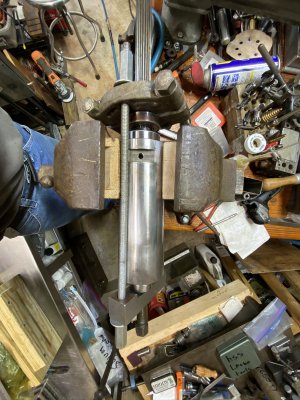
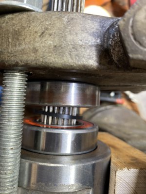
Here’s a pic of my coddled together bearing press/puller removing the last bearing. 12900FED-B256-4CEF-8B22-E07E5C7BE70E.jpeg63BA055C-01DD-49A9-A422-7EE08CBEE235.jpeg18B541C2-2FFD-48BE-9445-A499A51497C6.jpeg58646165-5C69-4F68-B0D6-4E41899E4A0B.jpegDBEB7C65-8209-43F0-9540-4694A4ACD55E.jpeg
 
Last edited:
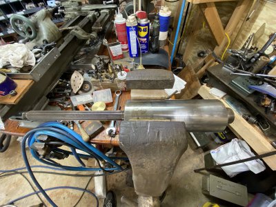
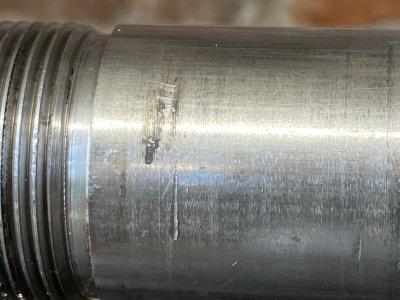
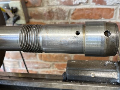
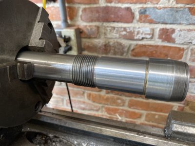
Still waiting on new bearings so figured I’d clean up the spindle. Everyone says that the bearings should be a “tap” fit. Whatever that means not exactly sure but I assume it means fairly snug so that the preload will work. But shouldn’t be a real press fit. My spindle had been repaired already and it had a few nicks. I lightly filed the high spots with a very fine jewelers file. I then mounted it in the lathe and polished it with a 600 grit belt sander.
Plenty of WD-40 while running the lathe at around 400 rpm.
BB5C5CF4-46FE-4043-BF60-9925E767E8F6.jpeg496A7D93-74EF-42F9-B37B-BE68F3D10D68.jpegDDD861C1-0E5A-4357-97BE-0D85EDB98C94.jpeg496A7D93-74EF-42F9-B37B-BE68F3D10D68.jpegDDD861C1-0E5A-4357-97BE-0D85EDB98C94.jpeg
 
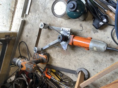
Here’s a picture of the belt sander and the end result of trying to fit one of the old bearings on the spindle. I just pushed it on by hand. It went on about a 1/4”. Before I polished the spindle I couldn’t get it started. I think this is good. After removing it again.... you can see where the bearing left it’s marks on the spindle surface. 5899C6A3-6EFD-434B-9C3B-68CB67AC3953.jpegD0DC8E38-A071-4CC2-94B7-E7EDBED2C0BA.jpeg
 
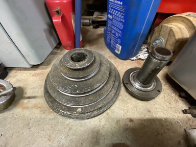
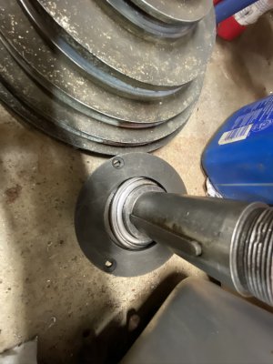
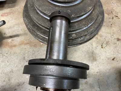
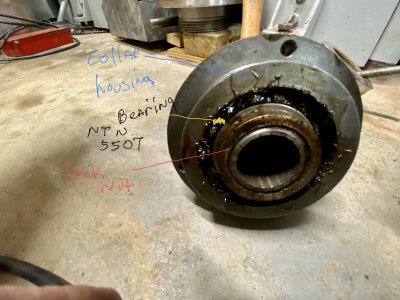
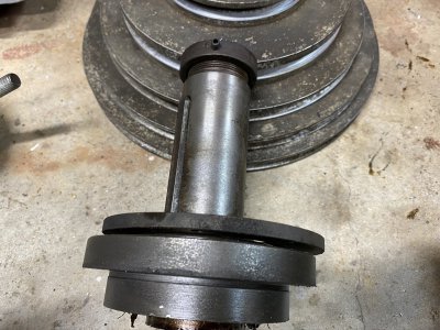
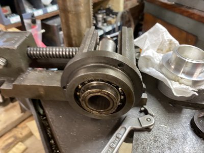
Removing the spindle itself is fairly straightforward. Once the motor is out of the way, then there’s a round nut which screws onto the top of the splined shaft that contacts the drawbar. Then mounted to the spindle housing is the #5507 bearing & collar on which the pulley is mounted. The pulley has female splines driving or actually being driven by the pulley which drives the spindle shaft. The pulley is kept on the collar by another threaded ring ( round ) locking nut. It has a set screw. It also has a hole which can be engaged by a pin wrench. I had said wrench and it came off easy. Once loosened, channel lock pliers make quick work of it. Then the pulley can be lifted off. This collar then has the 5507 bearing secured by a top plate and the 3 screws also secure this to the main housing. F7AAFD1A-CE97-4DD2-B78D-14F3E570CE8D.jpeg0F040B66-9F30-428A-AC4A-E1568F1C737A.jpeg1502D2F5-06A6-40EC-BB5F-372EBFC8FE8E.jpeg
 
This bearing actually feels good.Backside picture of the pulley bearing collar. There’s a locking nut that’s round securing bearing to collar. The grease hasn’t dried and I can’t feel any burrs or bad spots in this one. I’m probably going to just clean and repack this one.
Well, after cleaning it... it’s obviously bad. Has a bad spot which can be felt on every revolution. And yet with the grease in it, I could not feel this bad spot. There’s a lesson to be learned here. Always clean and inspect bearings.
FWIW, This is a double row ball bearing which supports the spindle pulley. My bearing is a Delco NDH bearing so I went on EBay and found a replacement.


2E16F1E3-368E-4847-B924-FA7A2B76313D.jpeg34A20BD0-908C-4D7F-848F-10F26A77DCF8.jpegBE4D8DCD-1277-4ED1-A7C1-186AAAD8F41E.jpeg
 
Last edited:
The bearing at the top end of the spindle on my mill is the worst of the bunch. It has a bad spot which I can feel a bump on every revolution. Very pronounced. Also...it was just a shielded bearing. The first thing I noticed is it was covered with a rusty oil. It occurred to me that whenever the exposed spline was oiled..... then the rusty oil travels down the shaft and accumulated on top of that shielded bearing. I’m going to go back and replace it with a rubber sealed Nachi ABEC-3 bearing part # “6206-2nse seals C-3.”
The old bearing is shielded one side only. But the problem is that the spline is always going to get lubed in my opinion. And that lube just passes through the shielded bearing. 79E277BA-6443-41E3-811B-93942F96835D.jpegD5F65C09-A2E4-40E0-8C93-2008277A611A.jpeg
 
Last edited:
I spent some time searching for precision bearings on EBay. Found the two 19268-3000 Timken cups for 40.00 each. Found one 19150-3000 for 110.00
And then I found another one...an open box for 14.95. Go figure.

This spindle was repaired once before. My bearings were all standard bearings. I installed the lower bearings which have the preload spacer and adjusted the preload. In the second picture, I’m just using the old 6206 and a little black spacer which makes contact with the inner race as a spacer for pressing the new bearing on the spindle. I do that so I’m not using the outer race of the new bearing as a pressure point while pressing the new bearing. It probably wouldn’t matter but that’s just a habit of mine whenever I press bearings. B604AE87-C534-4D17-8AF7-C287C8B2A376.jpeg9AB0F12B-0C01-4FF0-93D6-DDCCA9A779D9.jpeg
 
After I got the snap ring on, I ran into a problem. Once the lower quill nut was installed, the inner spindle would move in and out around a quarter of an inch. It took me a while to think about why this would happen. I disassembled everything, and tried reversing the bearing take-up nut because MikeAmick.com shows his quill with the take-up nut reversed. It’s got a big end with a lip and the other end is narrower. In the picture of him disassembling the quill, the nut has the end with the big lip ( or seat ? ) pointing away from the lower Timken Bearings. But on page two of his webpage shows that nut reversed.
Now, for what it’s worth.... the diagram also shows that nut with the big end pointing up , not touching the lower bearing race.
Long story short, when I tried reversing the nut.... with the big end pointing down, I could not access the set screws through the grease access Allen screw ..
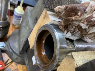
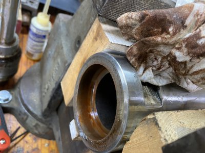
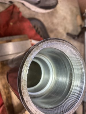
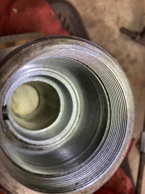
So I disassembled it again, and inspected my quill. I measured, inspected.... and then I saw it. I think that something went real bad at some point before I got my mill. Looking at my quill, I can see where there’s a big area worn away. I’ve read a couple of threads in which that take-up nut can back off if the set screws aren’t tight can back off and damage the quill or even lock up the the spindle.
And upon further inspection, I can see how the metal is even worn away into the lower threads of that Allen screw which gives access to the set screws when setting the preload of the spindle.
0AE60800-8F0F-4E2F-99F4-35996214187B.jpeg0F5D43CC-B1F4-40A5-9B05-32205C9D6D2C.jpeg
 
Last edited:
Back
Top