Millrite X-Axis power feed install

Tim9

H-M Supporter - Sustaining Member
H-M Platinum Supporter
Joined
Oct 11, 2015
Messages
1,196
Well, for the last two weeks I’ve been installing a power feed for my Millrite MVI milling machine. I took a number of pics of the install so I’ll document my installation in the next few days. For reference I looked at a couple of instructions on the net, including one on groups.io site and Bob Korves installation on this site.
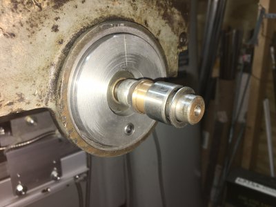
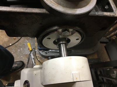
Bob removed the x-axis lead-screw for his installation and although I too felt this might be the best route in order to drill and install an extension, I thought I could avoid this step by going about it differently. The risk with my method is that there was a chance of ending up with an extension off center. Bobs install shows how he mounted a slightly oversized extension and then turned it true to the shaft on the lathe.
Call me lazy. Take your pick. In all honesty his method is probably best. But I didn’t want to go through that much trouble. So I’ll soon be posting some pics and showing how I went about it.
 
Last edited:
Look forward to it. I am in the near future going to retro fit a feed on my Fray mill. Just finished up with a 3 axis dro install.
 
First thing I did was clean up the Millrite end cap where the surface isn’t square. It’s just a rough casting from the factory but to mount the power feed the surface should be flat and square. I didn’t have my rotary table here.... it’s still at my old place. So I mounted the cap on a diy arbor. Stuck a collar on it but it would not tighten up enough so I loosened it....super glued surface and tightened it up. Mounted in lathe and since it was so out of balance I set lathe to back gear low speed. Cut it lightly @ 100 rpm.
I had to move position of QCTP to take two cuts. One at outer end of circle surface and then reposition tool post to cut the area around the center bushing
F3BAAC6E-C2A4-4B70-904C-F14098A7E420.jpegDB1AFD5E-A9B7-455F-AEE3-97F7CBB23F37.jpeg
 
I then cut an aluminum spacer to fill in that recessed area of end cap. Drilled a 1/4” hole about a half inch from edge. Fitted it into end cap and used a transfer punch through the hole to mark end cap. Tapped and mounted spacer. Then drilled an oversized hole to accept the center end cap mounting bolt. I also mad a bronze bushing which fit over the lead screw and fit inside the supplied bushing included with the power feed
 

Attachments

  • BFBD1418-F4EA-427B-AABE-5246E9226503.jpeg
    BFBD1418-F4EA-427B-AABE-5246E9226503.jpeg
    673.6 KB · Views: 23
  • C54C7EF2-1DCD-469D-A6C0-1A9357702C22.jpeg
    C54C7EF2-1DCD-469D-A6C0-1A9357702C22.jpeg
    504.7 KB · Views: 24
Next I drilled those two holes to mount the power feed. I mounted the feed on the bushing and rigged a clamp extended which held it in place while I used a transfer punch to mark positions of the two mounting bolts. That last picture tapped holes74218136-9BEA-4B3E-9E44-4C6B6DFC3641.jpeg
 
I then made an oversized length extension 5/8” diameter in which I just measured the total length needed for gear and handle once the feed is installed, and added about 1/4” length to it and pre drilled it while in the lathe so I knew hole would be straight and centered. I then used an oversized length drill bit I had.... about a 12” long 0.237” bit.
This extension was now my guide to drill the lead screw. It would act like a drill bushing. The way this worked is that the bevel gear of the power feed is a 5/8” bore gear. When I slipped the gear which is about 2.5” long it acted as a guide in which I could then slide the extension inside and this acted as a center guide for drilling the lead screw. I did have to add a .002 brass shim around both the screw and the extension so there was no play and then drilled the lead screw using that 0.237 drill bit to drill about a 3/4 depth hole in the screw. Sorry, I forgot to take pics of this.20C1C1AA-4095-4BC1-BC6B-0683CF4FE3E8.jpeg
 
No pics of me drilling the lead-screw but the above pic I posted shows the extension once I had drilled the lead-screw. I then mounted it back in the lathe and drilled it to final diameter center hole 5/16”
I then free-hand drilled the lead-screw for 5/16” threads. Since it was already drilled 0.237 , I only had to enlarge it for a 5/16”-18 threads tap. Used plenty oil and took it easy but wasn’t much to it. Used taper, plug then bottoming tap to thread lead-screw. I then mounted a long 5/16-18 rod threaded at one end and marked other end after installing all necessary items.... extension, handle etc. FWIW...I did have to make a few step keys for the extension as shown in above post pics. 4463CC50-41A8-44C0-B564-C2EF9B10C26C.jpegBD2A4590-B0BF-4928-BA72-FD75BABEE84F.jpeg
 
Last edited:
This is heroic. It took about 30 minutes to install a power feed on the Bridgeport X-axis. That was because I work slowly.
 
If you read the first post, it took me 2 weeks. I wish I could do it in 30 minutes.But in my defense the power feeds are designed for Bridgeports. Millrite is another animal.

I also wish I could document every step and post pics, but when doing the installation I was pulling my hair trying to figure out everything. And the Chinese instructions which came with my 120.00 EBay power feed suck big time.
Anyway, I got it on and it’s working good. Still need to mount micro switch safety stop. Still need to work that out.
 
Make sure you constrain and adjust out the end thrust on the lead screw. Does the 5/16" rod need to be that long, and for what?
 
Back
Top