Mini Lathe Crossfeed Nightmare

speedre9

Active User
Registered
Joined
Aug 26, 2013
Messages
167
This is a tale of woe. I got me a mini lathe from Grizzly sometime around 1998, I was excited. After experimenting and noodling I wanted to improve it, so this is where the nightmare began. The first thing I bought were the inch lead screw and nut offered by Micro Mark. That went well but it was for only the X and Y axis. I managed. Then came the Digital readouts for the cross feed. I installed them as instructed, it did not work as advertised. I never got an accurate reading, so I removed it and re installed it as instructed again, and then, again, three times total, still not correct. By that time it was to late to return it for refund or replacement. So long story short here's what I'm left with. A cross feed screw that binds and is now somehow 0.010" - 0.018" too long, plus it seems to rock on the ways when adjusted. Has anyone come up with a method of replacing this miasma of inaccurate and ungainly parts. I want to change the screw and the sucky nut arrangement:panic: to something more normal. Would someone want to start a dialog with me to explore this issue? I could really use some help with this.
 
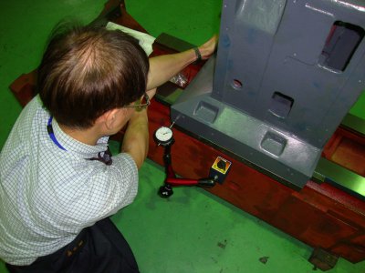
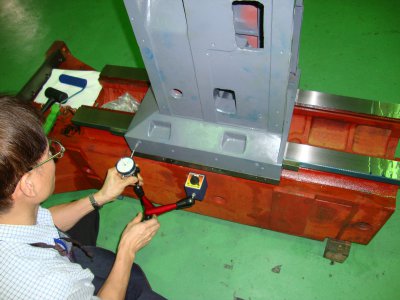
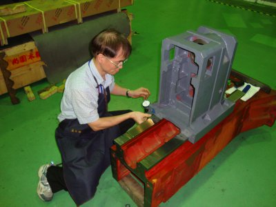
I can try to help but it would be nice to see some pictures. I have a couple of suggestions you can try too. I would loosen the outer feed screw braket. remove any dowel pins it may have. keep the bolts finger tight is all. Then crank the saddle out as far as it will go or as close to the feed screw brack as you can and then tighten the bolts. Have to checked the gib clearance with a dial indicator? If you haven't do that first. I will attach a couple of pictures showing how to do it. It's on a Column of a VMC, but the principle is the same. Check the gib on both ends . Push it release the pressure, set you indicator on zero, then pull the same spot toward you and release and the total indicator read after you push pull is the gap on the gib. You should not have more then .001" on both ends. If the saddle has a lock be sure it is loose. I would also loosen the feed screw bracket first to be sure it isn't binding. Do you own a parallel or better yet a precision blade square? You will lay it on the top of the table and indicate it in and see if the X and Y axis is square and as your .0005" dial Indicator moves along the straight edge of the square or parallel see if it you get a straight movement of your X & Y. I know this is hard to explain and read to understand. so if you need more help call me. 651 338 8141. If I can answer I will if not leave a message and I'll call you back when I can. Good luck, Rich

DSC00433.JPG DSC00432.JPG DSC00431.JPG
 
It sure sounds like the cross feed leadscrew nut has loosened.

"Billy G"
 
More info. The silly little brass nut that is on the feed screw, will not allow me to tighten it up. If I lock it down the screw binds madly and will not allow smooth advance of the tool holder. This is the main issue on my lathe. I can get the gibbs adjusted so's to have smooth advance, but that pesky little nut wants to be adjusted loosely. It seems that's the only way to get it to advance smoothly. As I write this I think I have a question that has been in front of me all along!
What if, I try to measure how much space is under the nut when it allows smooth advance, and shim it until I can lock it down so that the screw is in line with the nut? What do you guys think about that. Now the question is: how would I go about doing that??
 
It sounds are if it's a one piece nut? And the furture it move back the easier it is to move? Again a picture here or a print from the manual would be super helpful. You may want to tighten it until it move nice and then (not knowing what it looks like makes it a big quess) but measure the top of the cap screw where it is at with a dept mike or indicator and surface gage. Then tighten it and measure it again and that should be the thickness of the shim or close. Some machines has a 3 piece nut assembly the 2 outer pieces inner ends are made with a slight angle and the center piece is a wedged on both end. Different manufactures either have you push it down and other have you pull it up. All three have a fastener above it. This is a backlash eliminator nut. They are a pain to adjust, but it helps when the screw and nut get worn. If it is a 3 piece nut and the screw is worn you will have to make a happy medium because if you eliminate the backlash in the worn area and you move it to the unworn area it will bind up. If its a 1 piece nut do tes a couple of times. Once in with the slide 60% out from the front, make a shim and then test it closest to the operator. If you do it in one test you are taking a chance of bending the screw. Rich
 
More info. The silly little brass nut that is on the feed screw, will not allow me to tighten it up. If I lock it down the screw binds madly and will not allow smooth advance of the tool holder. This is the main issue on my lathe. I can get the gibbs adjusted so's to have smooth advance, but that pesky little nut wants to be adjusted loosely. It seems that's the only way to get it to advance smoothly. As I write this I think I have a question that has been in front of me all along!
What if, I try to measure how much space is under the nut when it allows smooth advance, and shim it until I can lock it down so that the screw is in line with the nut? What do you guys think about that. Now the question is: how would I go about doing that??

Take everything off the cross slide. Adjust the location of the nut with shims till you get the movement you seek. Once you have the nut locked down and the leadscrew moving smoothly you are ready to put it back together. Should be an easy fix.

"Billy G"
 
Getting a picture of want this is, is nigh impossible. The nut is a small square piece of brass about .56" sq. with two taped holes for adjustment screws. It can be adjusted up, down and on an angle. It is that very capability that must be contained. These two screws are screwed, into the nut thru the cross feed way casting with a centered tightening cap screw counter sunk to be beneath the top surface. So the nut essentially floats upon that center screw like a seesaw, oh and it also takes out almost all the 0.01 - 0.018 slop in the lead screw when engaged. I think the main problem I've found is, the inability to properly center and lock the nut in place. I guess I will have to use some Yankee ingenuity to solve this. Having this dialog has helped work my way thru this, now all I got to do is get it done. Thank you very much.
 
It's a guessing game for us to help with-out a picture or a page out of your manual, take it apart and snap a picture if you want our professional opinions. If this what you have to do, I would do the adjustment as close to a support bearing and I am assuming that would be when it is closest to the operator. Then I believe as all of us have said, shim it solid so if the set screws change or get lose after you know how much you need. In the majority of those small machines you can screw the cross-slide (that's what we call the casting) and then measure the gap with a feeler gage and make a shim out of brass, steel or plastic shim-stock.

Ray and Bill are experts on these small imported lathes as they both own them, do repairs on their machines and have been advising the membership for years. But they, like I are limited to our imagination with out a picture of the lathe as there are several brands and models that are all different. If you need any more help, we're here for you. Rich
 
Back
Top