Mini lathe saddle ways are convex?

KKrum

Registered
Registered
Joined
Dec 25, 2021
Messages
21
When I originally got my mini lathe, I took it completely apart and cleaned off the grit (a huge improvement) but I didn't know what to look for in terms of fit and finish. A year later, in a quest to better understand and improve my machine, I took apart the cross slide, cleaned everything, and test fit the slide without the gib, pressed to one side as it would be with the gib installed. I found that the cross slide rocks front to back on the saddle ways. I believe the saddle ways are convex because I placed the cross slide on the bed ways and it doesn't rock, and I placed a straight edge on the saddle ways and it does rock.

I found a somewhat related thread, but the problem there seemed to be the gib. Should I be thinking about scraping my saddle ways? Is this even a significant problem? It occurred to me that maybe it's worse for the ways to be concave than convex, so maybe they're intentionally slightly convex to allow for more wear. But I'm just spitballing.
 
These mini lathes are known for having machining problems. It may be that the castings were not aged and warped after machining. If you can scrape the slides and improve it, go ahead.
You may want to practice on some scrap cast iron first
 
I got some high spot blue and confirmed that the ways were convex. I stoned and scraped them and got them much flatter front to back. The right side in my drawing makes good contact. That's the gib side. The left side still has a problem. Originally the cross slide was riding on a high spot on the left side close to the left edge. Now the only point of contact is a high spot down in the dovetail where I can't reach. I can shine a light in the back and see it in the front.

Possibly stupid ideas in my amateur machinist brain:
  • Grind the corner off the cross slide dovetail
  • Cut a slot in the apex of the saddle dovetail
  • Shim the dovetail on the left side - not sure there's enough room to clear the high spot
  • Shim the left way so it's higher than the high spot
For shims I was thinking of self-adhesive aluminum flashing tape. Would that work or just immediately wear out?


dovetail.jpg
 
I did what I probably should have done in the first place, took some measurements. I don't have a surface plate or any other really flat reference except the bed ways of this lathe. (If they're flat.) As I mentioned before, the sides of the cross slide are ground flat enough that they sit on the ways with no rocking or gaps. The edge of the cross slide also shows the top of the saddle dovetail to be relatively flat. They probably ground it for cosmetic reasons. I thought maybe I could learn more about the shape of the ways by measuring their height relative to the top of the dovetail.

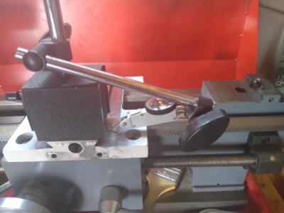
First I set up a test indicator on the base of my tailstock to see how flat the top of the dovetail is from left to right, moving the carriage, not the tailstock. I arbitrarily called the left side zero. Each pair of measurements is independent of the other pairs, so this is not an indication of flatness from front to back. Then I put the indicator holder on top of the dovetail and measured its height above the ways at several points.

Although I've probably ground .002 from the middle third of the ways, they're still convex. I've touched the front and back thirds very little or not at all. You can still see the original cutter marks there.

Relative to the left side, the right side of the dovetail reads front to back (in thousandths):
0, 1, 0.5, 1, 1.5

Using the top of the dovetail as a reference, the right way reads front to back with an arbitrary zero:
-2.5, 0, 2, 3.5, 4.5, 6, 8, 8, 6

And the left way:
-0.5, 1, 3.5, 5, 7, 8, 9, 9, 6

So the left and right ways are close to being the same profile. And the high points shown by these measurements agree with the high points I feel by rocking and rotating a straight edge on the ways. I don't think I should try to make the ways parallel to the top of the dovetail. I think I should grind away that big hump about 2/3 back and aim for a steady height increase from my zero mark in the front to .006 in the back, or about .001 per inch. Yeah?


setup1.jpg
setup2-jpg.415405
result.jpg
 

Attachments

  • setup2.jpg
    setup2.jpg
    30.2 KB · Views: 451
Last edited:
Maybe one of the rebuilders can chime in, but I think the saddle ways mainly need to be flat and perpendicular to the spindle axis. Front and back tilt shouldn’t matter that much.

I think you need to think about the slanted part of the dovetail ways vs the flat part. If you lower the flat part at the back of the saddle ways then the dovetail will become effectively narrower there as well. You can measure this over dowel pins.

A small surface plate is pretty cheap, compared to a mini lathe. Like forty bucks cheap. If you’re gonna spend the time to make this right it’s probably worth getting one.
 
If you have a triangular-shaped carbide insert lying around you can mount one on the end of a rod to get down into the corner of the dovetail. Ideally the scraper should be curved to confine its cutting action to a small region but in your case I think you just want to knock off that raised area.

Since that side has the gib in it, I don't think you need to worry about grinding a relief into the inside corner of the dovetail. If it appears to be an issue, modify the gib.

Ideally, you want an angled reference surface that can get in there to mark the high spots. The angle doesn't have to match the dovetail angle, it just has to be a little less to ensure that you _can_ get in there. These things usually are shop-made for the purpose, then scraped flat using a surface plate.
 
I got a piece of grit under the saddle and scratched my back way, so I decided to rebuild it again and revisit the saddle fit. I've been watching YT vids about Chinese mini lathe problems and mine seems to have all of them. My front and back ways are tapered .004 in thickness just like Aussie Shed's. Back thicker toward the headstock, front thicker toward the tailstock. My saddle is also tilted downward toward the back like Aussie Shed's and another YTer whose name I forget at the moment.

I've acquired two vintage precision straightedges. As I thought, the top of the saddle dovetail (a non-contact surface) is ground pretty smooth and flat. I think this was supposed to be the reference for the other surfaces, but they clearly didn't use it. I used the straightedges to prop my mini jeweler's vise above the prismatic ways and set an indicator on top of that to take measurements of the saddle.

My saddle is really bad... 0.040 down in the back! Clamped down on the front prismatic way, I can't get a .0015 shim in on the back headstock side but a .007 shim goes in with drag on the back tailstock side. Blued up and printed, the back is really only contacting on a very narrow strip on the headstock side and back edge. On the front way, it's contacting very well on the back side (toward the work) but barely at all on the front side.

If I put a .020 shim on the back way, the front side of the front prismatic way gets better but the back side (originally good contact) gets worse.

I got some 22 gauge mild steel. It should be about .029... I'll mic it to be sure. My plan is to JB Weld two pieces of that steel to the rear bearing surface of the saddle, then lap and/or scrape in the front contact surfaces.
 
Back
Top