- Joined
- Dec 18, 2019
- Messages
- 6,426
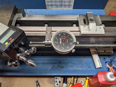
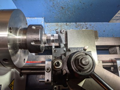
As is usual for most mini-lathes, my mini-lathe tailstock is pretty far out of adjustment. I couldn't seem to get a decent repeatable setup, especially with the stock configuration. So I've designed up a variation of a cross axis adjustment that has reasonable adjustment range and a fine adjust. Looking at some resources on both HM and Little Machine Shop, I've come up with an adjuster that has +/- 6.3 mm coarse adjustment with a fine adjust of 0.25 mm per turn. Now, I realize there are other errors in my tailstock like height, pitch and yaw, but one needs to try to attack a problem at a time...
LMS tailstock adjuster
petcnc's tailstock mods
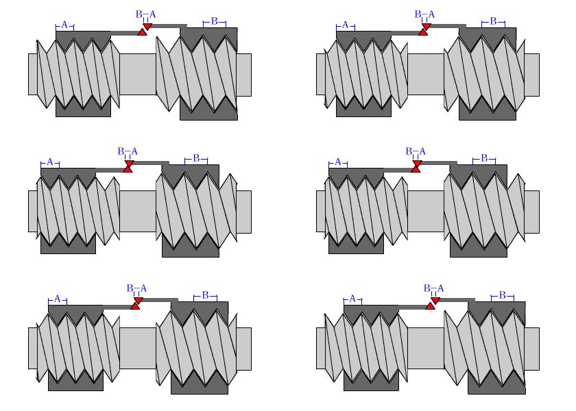
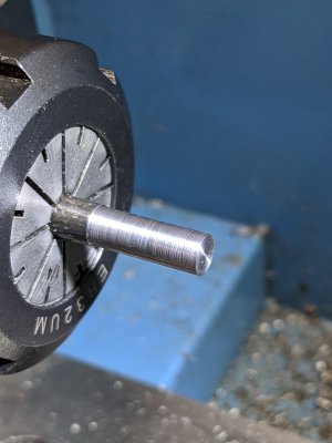
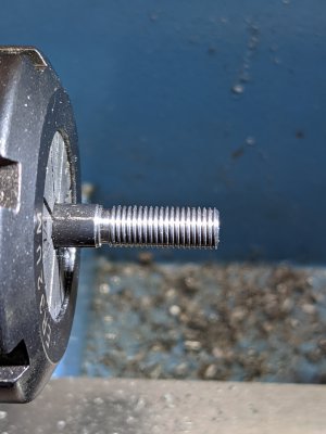
The 250 micrometer per turn comes about from using a differential screw. That is a screw with two different threads. I chose a size that I could easily thread that had available taps in both a coarse and fine pitch. In my case I chose M6, which has a standard thread of 1mm pitch, and a fine pitch of 0.75mm. If one makes this choice, and uses one nut on the adjuster bar and a threaded hole in the mini-lathe base threaded with the other pitch, as one turns the screw clockwise, the base will approach the nut 250 micrometers for a single turn. This should be sufficient to have a reasonable fine adjust. There is no free lunch with this, so one needs to account for the travel of the screw, which advances in each nut by its pitch for every turn. It is for this reason that I decided to thread the base with the fine pitch, as there is limited travel on this side. Eventually the screw will interfere with the tailstock clamp that holds the tailstock to the ways. My design has 16T of fine adjustment, which corresponds to 4mm or +/- 2mm. The fine thread has 20T giving me 4T of engagement in the tailstock base.
One could use M5 which has a 0.8 and 0.7 pitch, but I wasn't comfortable with single point threading the 0.7 pitch. One needs a sharply honed tool with minimal flattening to SPT these pitches. My first attempt at this showed me this very fact. Had enough fun with the 0.75 pitch. I made the screw, but I will remake it as the coarse thread needs to be a little longer. I also made the M6x0.75 a little undersized, as it was my first use of thread wires. (The screw was pretty sloppy in a M6x0.75 threaded hole.) Now that I understand what to do, the next (third) attempt will be a lot easier! I don't know why, but I made the screw out of O-1 steel. Guess it was the first stock I saw. Afterwards, rummaging through my rod stock found some 12L14 and 1144 in 1/4". Maybe I will use the 1144 for the next try. Probably single point thread a little easier!
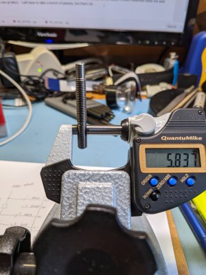
What is nice about the basic LMS design is that the nut is not threaded to the adjuster, it can freely rotate in the slot. This means a coarse adjustment can be made by simply spinning the nut (and holding the screw). So 1 turn of the nut is 1 mm of displacement. When fine adjustment is needed, then the nut is captivated by a wrench and the screw is turned. At some point I may put a bar or keeper to prevent the nut from turning. Just don't know how much of an issue it might be.
My choice of M6 meant that I could not directly use the LMS tailstock design. I slightly modified it to allow the use of larger screws. Attached is a dxf file. There are different layers that one can selectively turn on to see the details. With all layers on, the drawing is a mess. But it was the only way that I could tell if things were going to work. My original design had a 1/2" hex for a nut. It would work, but the nut only hung over the edge by 0.0625", so I decided to use a 5/8" nut instead. That way there would be a 0.125" minimum overlap. I put in the larger nut, but haven't modified the nut view in the drawing yet.
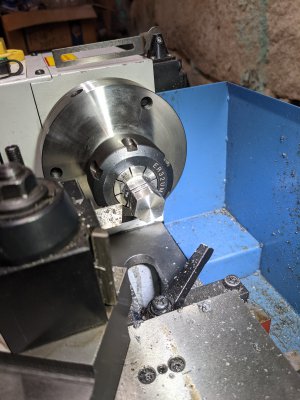
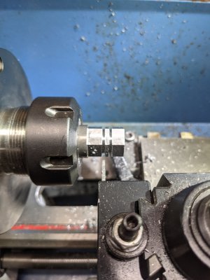
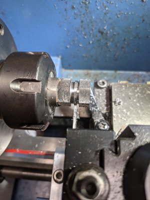
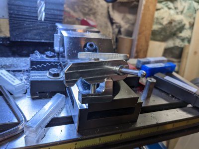
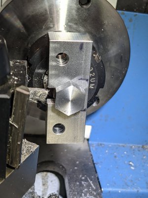
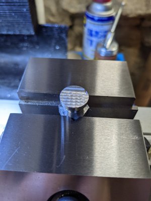
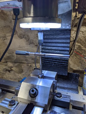
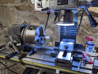
Don't have any 5/8" hex stock. I know I bought some 3/4", but for the life of me couldn't find it. You'd think it was hard to lose a foot of 3/4" hex. I had some 1/2" hex, but that's too small. So I decided to make some. Dusting off the cobwebs, determined that I could make 5/8" hex from 3/4" round stock. Thought it would be a good excuse to use my BS-0 for the first time. Sure I could have used a hex sided collet, but I needed to try the BS-0. So set up the BS-0 on my mill and made a short section of hex. I had no idea if 0 degrees indicated on the BS-0 was actually zero, but it turned out it was well under 0.0005" in pitch, which is good enough for this short piece. I did need to pull out the end mill a bit, so there was some clearance between the BS-0 chuck and the spindle light. Just barely cleared the edge of the 3 jaw chuck jaws, when cutting the hex.
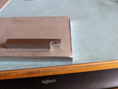
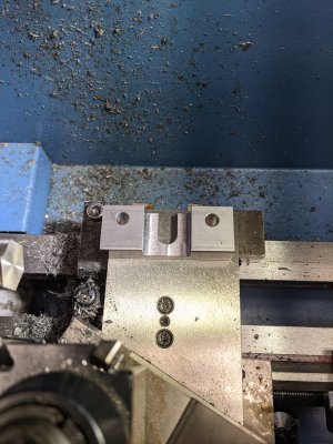
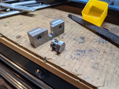
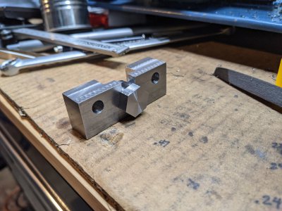
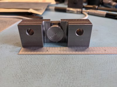
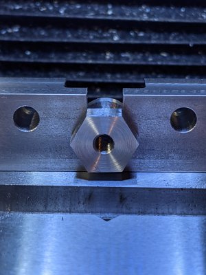
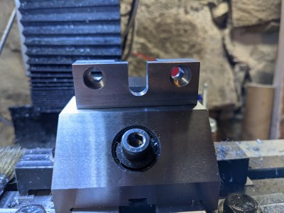
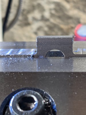
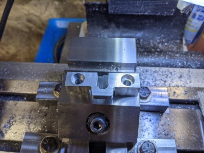
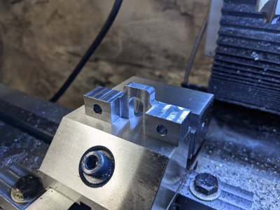
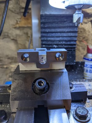
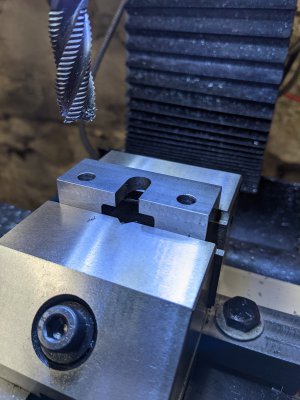
The adjuster is in the vise. I am waiting for an end mill to do the counterbore. I made the slot with a 5/16" end mill, widening it to 3/8". When it was really close, within a few thousandths, I ran a 3/8" end mill in the slot. A 0.375" rod just barely drops into the slot. After the counterbore I will cut away both sides, making a tab for the slot. In this picture it would be the far edge on either side of the slot. The width needs to be reduced to 14mm so that the bottom of the tailstock base clears. In my design, the slot is from the top. The LMS design the slot is from the bottom.
That's all I have for now. I struggled thinking out the order of operations (found in the notes in the drawing). Hoping that reasoning will speed up in the future. While I am waiting for the end mill, I will make the nut. Without a centered tailstock it won't be easy to center the bore of the nut. I can drill it on the mill, but I am not sure how to center the nut accurately across the points of the hex. Can an edge finder work on a 60 degree edge? Freshly milled, it is pretty sharp.
Later, I found the 3/4" hex stock... It was on the shelf - in plain view, but in a slightly different place. Funny, it was invisible to me for a day and a half!
To be continued.
LMS tailstock adjuster
petcnc's tailstock mods
The 250 micrometer per turn comes about from using a differential screw. That is a screw with two different threads. I chose a size that I could easily thread that had available taps in both a coarse and fine pitch. In my case I chose M6, which has a standard thread of 1mm pitch, and a fine pitch of 0.75mm. If one makes this choice, and uses one nut on the adjuster bar and a threaded hole in the mini-lathe base threaded with the other pitch, as one turns the screw clockwise, the base will approach the nut 250 micrometers for a single turn. This should be sufficient to have a reasonable fine adjust. There is no free lunch with this, so one needs to account for the travel of the screw, which advances in each nut by its pitch for every turn. It is for this reason that I decided to thread the base with the fine pitch, as there is limited travel on this side. Eventually the screw will interfere with the tailstock clamp that holds the tailstock to the ways. My design has 16T of fine adjustment, which corresponds to 4mm or +/- 2mm. The fine thread has 20T giving me 4T of engagement in the tailstock base.
One could use M5 which has a 0.8 and 0.7 pitch, but I wasn't comfortable with single point threading the 0.7 pitch. One needs a sharply honed tool with minimal flattening to SPT these pitches. My first attempt at this showed me this very fact. Had enough fun with the 0.75 pitch. I made the screw, but I will remake it as the coarse thread needs to be a little longer. I also made the M6x0.75 a little undersized, as it was my first use of thread wires. (The screw was pretty sloppy in a M6x0.75 threaded hole.) Now that I understand what to do, the next (third) attempt will be a lot easier! I don't know why, but I made the screw out of O-1 steel. Guess it was the first stock I saw. Afterwards, rummaging through my rod stock found some 12L14 and 1144 in 1/4". Maybe I will use the 1144 for the next try. Probably single point thread a little easier!

What is nice about the basic LMS design is that the nut is not threaded to the adjuster, it can freely rotate in the slot. This means a coarse adjustment can be made by simply spinning the nut (and holding the screw). So 1 turn of the nut is 1 mm of displacement. When fine adjustment is needed, then the nut is captivated by a wrench and the screw is turned. At some point I may put a bar or keeper to prevent the nut from turning. Just don't know how much of an issue it might be.
My choice of M6 meant that I could not directly use the LMS tailstock design. I slightly modified it to allow the use of larger screws. Attached is a dxf file. There are different layers that one can selectively turn on to see the details. With all layers on, the drawing is a mess. But it was the only way that I could tell if things were going to work. My original design had a 1/2" hex for a nut. It would work, but the nut only hung over the edge by 0.0625", so I decided to use a 5/8" nut instead. That way there would be a 0.125" minimum overlap. I put in the larger nut, but haven't modified the nut view in the drawing yet.
Don't have any 5/8" hex stock. I know I bought some 3/4", but for the life of me couldn't find it. You'd think it was hard to lose a foot of 3/4" hex. I had some 1/2" hex, but that's too small. So I decided to make some. Dusting off the cobwebs, determined that I could make 5/8" hex from 3/4" round stock. Thought it would be a good excuse to use my BS-0 for the first time. Sure I could have used a hex sided collet, but I needed to try the BS-0. So set up the BS-0 on my mill and made a short section of hex. I had no idea if 0 degrees indicated on the BS-0 was actually zero, but it turned out it was well under 0.0005" in pitch, which is good enough for this short piece. I did need to pull out the end mill a bit, so there was some clearance between the BS-0 chuck and the spindle light. Just barely cleared the edge of the 3 jaw chuck jaws, when cutting the hex.

The adjuster is in the vise. I am waiting for an end mill to do the counterbore. I made the slot with a 5/16" end mill, widening it to 3/8". When it was really close, within a few thousandths, I ran a 3/8" end mill in the slot. A 0.375" rod just barely drops into the slot. After the counterbore I will cut away both sides, making a tab for the slot. In this picture it would be the far edge on either side of the slot. The width needs to be reduced to 14mm so that the bottom of the tailstock base clears. In my design, the slot is from the top. The LMS design the slot is from the bottom.

That's all I have for now. I struggled thinking out the order of operations (found in the notes in the drawing). Hoping that reasoning will speed up in the future. While I am waiting for the end mill, I will make the nut. Without a centered tailstock it won't be easy to center the bore of the nut. I can drill it on the mill, but I am not sure how to center the nut accurately across the points of the hex. Can an edge finder work on a 60 degree edge? Freshly milled, it is pretty sharp.
Later, I found the 3/4" hex stock... It was on the shelf - in plain view, but in a slightly different place. Funny, it was invisible to me for a day and a half!
To be continued.


