Model 1925 setting up for metric threading question

Gadgetologist

Registered
Registered
Joined
Dec 14, 2015
Messages
6
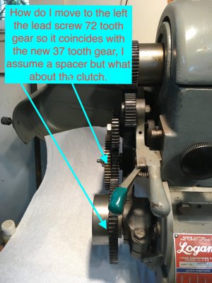
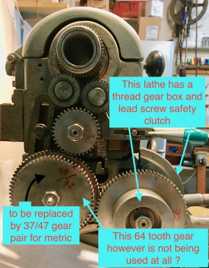
I wish to setup my Model 1925 made in 1964 to cut metric threads. I want to use the 37/47 gear pair which are readily available. However the issue I have is it has a quick change gear box and a lead screw safety clutch. There does not seem to be enough room to put a spacer in there to move the lead screw gear to the left to match the 37 tooth gear. Here are a couple of photos. By the way what is the current 64 tooth part of 64/72 gear used for in its current configuration. Right now it engages with nothing.

IMG_0438.jpgIMG_0439.jpg
 
Do these help? This info on metric threading came from Logan's website.
There's a diagram of gear train setup.
 

Attachments

  • crvs image (dragged).pdf
    197.1 KB · Views: 18
  • crvs image-1.pdf
    450.3 KB · Views: 20
Last edited:
Yes I have seen those first thing. Not very informative in reality. The pitch chart will be nice once I get the gears in the right place. The side to side spacing of the lead screw gear is the main question. Thanks though for the info.
 
Can the gearbox gear and clutch assembly be removed and turned around so that the gear engages
the 37 tooth gear? If I'm reading the chart right, you need a 60 tooth gear on the gearbox.

Here's another document on metric threading. Not sure what's in there since I can't open an .xls file, but
it might be helpful if you can.

You could always call or send an email to Logan for clarification.
 

Attachments

  • Metric Lathe threading 20170424.xls
    2.3 MB · Views: 19
Last edited:
You cannot simply turn the screw gear and slip clutch around because it appear from the side view photo that the slip clutch is about 1.5 times the thickness or face dimension of all of the gears.

There may be better ways to do it, and the following is in the first instance only intended as an example of how to make the 72T screw gear mate with the smaller of the two gears making up the compound gear. If you replace the unknown tooth count gear that is driven by either the FWD or REV idler gears with one with twice the face dimension, replace the screw or shaft that the idler gear runs on with one that is longer by one face dimension, and turn the 72/64T compound gear around, the screw gear will then line up with the 64T gear instead of the 72T.

Then replace the 64/72T gear with the 37/47T one that you mentioned, loosen the Banjo clamp and slide all of the gears back into mesh and re-tighten everything. This all assumes, of course, that the slip clutch will not touch the 47T gear before the screw gear meshes with the 37T. I don't have the parts to check that.
 
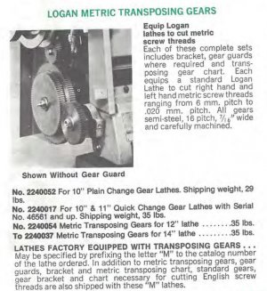
I'm looking at a photo of the transposing gears from a later Logan-Powermatic catalog. It shows the gear on the lead screw engaging
the smaller gear to the outside (37T). The gear on the lead screw is attached to the shaft with no clutch shown. I wonder if the clutch
needs to be removed and the gear bolted directly to the shaft?

Sorry, I can't find a way to post the photo: it's part of a large PDF which is too big to post to the thread. If you contribute to the site,
you can look in Downloads at the 1980 Logan Catalog and you'll see it.
 
Last edited:
This is from the 1980 Logan catalog. FYI i used the "Snipping Tool" which is part of Windows 10. LoganMetricTrans1980cat.JPG
 
Can the gearbox gear and clutch assembly be removed and turned around so that the gear engages
the 37 tooth gear? If I'm reading the chart right, you need a 60 tooth gear on the gearbox.

Here's another document on metric threading. Not sure what's in there since I can't open an .xls file, but
it might be helpful if you can.

You could always call or send an email to Logan for clarification.
I opened that file. There was also a diagram of the change gear locations.
16
0.039370
16
18
24
32
36
40
44
46
48
52
54
56
60
64
72
For Gear Boxes where the Gear Box Gear is defined as double the Stud Gear​
Metric Tread​
Metric TPI​
Actual TPI​
Stud Gear​
1​
2​
3​
4​
Gear Box Gear​
set Gear Box to​
Gears Fit​
ERROR %​
0.20
127.0000​
126.9841​
56​
40​
54​
48​
24​
60​
160
PASS​
0.0125​
0.225
112.8889​
112.8748​
56​
64​
54​
40​
18​
60​
80
PASS​
0.0125​
0.25
101.6000​
101.5996​
18​
40​
36​
56​
46​
52​
52
PASS​
0.0004​
0.30
84.6667​
84.6561​
36​
64​
56​
40​
18​
60​
40
PASS​
0.0125​
0.35
72.5714​
72.5711​
36​
40​
54​
52​
46​
60​
104
PASS​
0.0004​
0.40
63.5000​
63.4921​
56​
40​
54​
1​
1​
60​
160
PASS​
0.0125​
0.45
56.4444​
56.4374​
56​
64​
54​
40​
18​
60​
40
PASS​
0.0125​
0.50
50.8000​
50.7998​
18​
40​
36​
56​
46​
52​
26
PASS​
0.0004​
0.55
46.1818​
46.1825​
56​
46​
36​
1​
1​
44​
92
PASS​
0.0016​
0.60
42.3333​
42.3280​
36​
64​
56​
40​
18​
60​
20
PASS​
0.0125​
0.70
36.2857​
36.2856​
36​
40​
54​
52​
46​
60​
52
PASS​
0.0004​
0.75
33.8667​
33.8665​
54​
40​
46​
56​
36​
52​
52
PASS​
0.0004​
0.80
31.7500​
31.7460​
56​
40​
54​
1​
1​
60​
80
PASS​
0.0125​
0.90
28.2222​
28.2187​
56​
64​
54​
40​
18​
60​
20
PASS​
0.0125​
1.00
25.4000​
25.3999​
18​
40​
36​
56​
46​
52​
13
PASS​
0.0004​
1.00
25.4000​
25.4000​
32​
127​
100​
1​
1​
64​
20
PASS​
0.0000​
1.12
22.6786​
22.6800​
60​
54​
40​
1​
1​
56​
18
PASS​
0.0063​
1.25
20.3200​
20.3199​
72​
32​
36​
56​
46​
52​
52
PASS​
0.0004​
1.40
18.1429​
18.1428​
36​
40​
54​
52​
46​
60​
26
PASS​
0.0004​
1.50
16.9333​
16.9333​
54​
40​
46​
56​
36​
52​
26
PASS​
0.0004​
1.60
15.8750​
15.8730​
56​
40​
54​
1​
1​
60​
40
PASS​
0.0125​
1.75
14.5143​
14.5142​
46​
32​
54​
40​
48​
52​
52
PASS​
0.0004​
2.00
12.7000​
12.6999​
72​
40​
36​
56​
46​
52​
26
PASS​
0.0004​
2.25
11.2889​
11.2892​
64​
54​
52​
46​
32​
44​
22
PASS​
0.0029​
2.50
10.1600​
10.1600​
72​
32​
36​
56​
46​
52​
26
PASS​
0.0004​
3.00
8.4667​
8.4666​
54​
40​
46​
56​
36​
52​
13
PASS​
0.0004​
3.50
7.2571​
7.2571​
46​
32​
54​
40​
48​
52​
26
PASS​
0.0004​
4.00
6.3500​
6.3500​
72​
40​
36​
56​
46​
52​
13
PASS​
0.0004​
4.50
5.6444​
5.6446​
64​
54​
52​
46​
32​
44​
11
PASS​
0.0029​
5.00
5.0800​
5.0800​
72​
32​
36​
56​
46​
52​
13
PASS​
0.0004​
Maximum Thread
4480.0000​
18​
60​
24​
64​
16​
72​
224
PASS​
This is what that file looks like.
 
I'm looking at a photo of the transposing gears from a later Logan-Powermatic catalog. It shows the gear on the lead screw engaging
the smaller gear to the outside (37T). The gear on the lead screw is attached to the shaft with no clutch shown. I wonder if the clutch
needs to be removed and the gear bolted directly to the shaft?

Sorry, I can't find a way to post the photo: it's part of a large PDF which is too big to post to the thread. If you contribute to the site,
you can look in Downloads at the 1980 Logan Catalog and you'll see it.
Hello all, I'm new here, this is my first post ... Metric Threading Conversion for the Logan Lathe ...

I am also adapting my Logan Model 1957 QC lathe to cut metric threads, after many years of languishing over the project ... Years ago I obtained the new/spare change gears needed from Dave Sobel (Closter, NJ) and Boston Gear, 20+ years ago now; (two 60T's, 37T, 42, 47,48 and a 54 tooth) 16 pitch, 5/8" bore, 5/32" key-way gears) ...there are 39T and 66T stud gears 'called out' on the Logan chart, but are for odd-ball metric pitches I'll prolly never need anyway, so I don't need those gears .... The Logan Metric chart is available on-line.

This chart shows the ISO standard metric pitches as asterisked, so my gears, as listed above, cover those.

My lathe came from a school, and had the optional Logan LA-774-1 'Automatic Safety Gear' (safety clutch) installed on the leadscrew (like in the photo from originating post), so in case of a crash by the kids, any damage would be minimal! This assembly has a solid steel 72T gear as an integral part of the safety clutch assembly.

This safety clutch is removed from the leadscrew by removing the 3/4" nut with a socket, and the clutch/72T screw-gear assembly will slide right off... be careful not to lose the small woodruff key!

The metric transposing gear-pack assy (47/37T gears keyed together on a bushing) requires that the new 60T 'screw gear' to be spaced out on the end of the lead-screw, to mesh properly with the 37T transposing gear. Two spacer washers need to be machined to achieve the proper gear-face spacing, with a 5/8" bore, one washer with a keyway and the other plain, to properly space the gears. Use the plain spacer washer (approx 1/8" thick by 1-1/8" dia. ?) first against the gearbox, then a spare new unused change gear against the QC gearbox, then the woodruff key and then slide on the new 60T screw gear and snug-up the 3/4" nut. The safety clutch/72T assy is not used to cut metric threads, but will be re-installed to return to SAE threading. I plan on machining the two new 'screw-gear' spacer washers from cast-iron barstock.

I ordered a new change gear bushing (LA-231) and 5/32" key (LA-249) from Logan Actuator Co. to assemble the 47/37 transposing gear pack, to keep it together for convenience, rather than dis-assembling the std. 64/72T pack assy that came as std. with the lathe. A new thin spacer washer may need to be machined to space the transposing gears on the new bushing (I'm awaiting parts from Logan now).

Some of my new change gears came from Boston Gear; these come std. with a 3/4" bore and double 3/16" keyways, so unusable as-is.... I'll bore-out these gears, and re-bush. I'll machine new bushings from 1-1/4" dia. cast iron barstock, bore/ream 5/8" and cut the required 5/32 keyways in the new 47 and 37 and 42T (stud) Boston gear bushings. Then press-in/Loctite the new bushings into those three gears. The other change gears are original NOS Logan gears that Dave S. had....

I know, this is a longish first post, so I apologize!! But maybe it can help someone out here.... If I run into any snags with this project, I will advise on this thread as I go along.

John B.
 
Back
Top