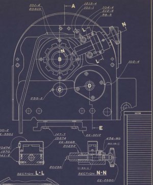
Thanks Rabler. I checked that out but not much luck. The 65 manual you mentioned does have a blueprint drawing of the electric lockout for the spindle lock but not enough detail to understand. The bolt mounting is vertical also compared to yours a year earlier. Cross section N-N shows what appears to be a plunger-type micro switch that is NC when extended (lockout pin retracted). Bill
I haven't disassembled mine but that diagram looks to match mine in every detail. I'm not sure what you mean about bolt mounting, but it does look like the mounting bolts are both on the spindle side with the pins being farther away, whereas yours the bolts and pins are in diagonal corners.
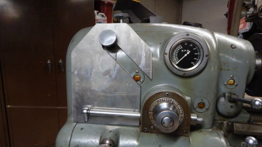
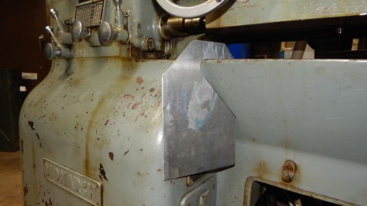
There is a microswitch mounted on the casting for the lockout. It is on the side farthest away from the vertical face of the headstock. There is a sheet metal shroud covering the switch. I would assume the shroud is there because the switch terminals are line voltage in the Monarch implementation. The wires from the switch run in a small tube/conduit, over the top of the spindle and down the back side of the headstock.
I'd think with a low voltage VFD switch, you could drill a small hole in the casting for a plunger type microswitch, going in from the face farthest from the headstock. Then drill two small blind holes and tap to something like #4 screws on either side of that hole to retain a switch. You can get pretty small switches for low voltage. Then you'd have to figure a way to get a ramp onto the actual spindle lock shaft.