Monarch 1944 12" CK

Thanks for the idea on the vfd. When I finally finish the vfd conversion of the 1024, I need to finish up the 60/61 and was dreading the wiring. My motor is 1800 and the top speed is 700 rpm. Monarch used the same bearings for the 1000 top speed machines so I think I will swap a pulley and use a vfd. Your colors turned out way better than mine but they are here to stay. I clear coated the enamel with Spraymax auto paint that even acetone won't touch so I'll live with the mistake.

Cleaned up and well cared for isn't a mistake. ;)
I really like the Monarch 61's and would consider them the ideal large home shop lathe. Obviously if you swap out the pulley for higher RPM, you do loose some torque. But that may not even be noticeable for most general purpose work, only if you are trying to remove metal by the pound, as those machines were originally intended for.

How do you like the clear coat? I've thought of doing some sort of clear coat on mine. How fast did the clear coat set up?
 
Hi Rabler,
I just got around to reading this thread. It was very interesting and it looks like you are doing nice, thorough work. I bought that same lathe a couple of months ago. It was built in May of 1942 - about the time of the battle of the Coral Sea. I also have an old milling machine from that era. It was built 4/42 - during the Doolittle raid. (I'm a student of the Pacific War - where a Lot of this machinery was first sent)
You mentioned you bumped up the spindle speed on yours. The one thing I can add to that is mine was factory 1000 rpm spindle speed so I doubt you'll hurt it running it faster.
I have not done much with mine. Replaced the felt wipers and did some cleaning. Need to change oil in the headstock yet. The apron pump is putting plenty of oil to the ways but not sure of other areas yet. I don't plan to tear into it unless I need to.
From looking at other photos of these lathes one thing I have not often seen is a carriage travel indicator which mine has. (Photo) Must have been an option. A fellow I've gotten to know recently here in the Twin Cities also has a 12CK and his does not have that indicator or the feed reversing handle on the carriage that ours has. So that must have been optional as well.
Mine has the 3 hp motor. I built a RPC to power it as my mill is 3 phase too so I can power them both .
I saw somewhere, maybe on PM? that you'd picked up a 12CK. I read that they were available in 1000RPM. I can run mine to a max of about 1100RPM with the setup I have, although rarely do I feel the need for more than 800. I'd heard someone say that it they were available up to 1000RPM spindle but had never seen a gear shift plate from one that was set up that way. Thanks for posting yours. The travel indicator is neat, but I've mounted a DRO on mine so it wouldn't add anything. Just interesting to see the options on these.

What year is the the other 12CK? I had thought the feed reversing handle was standard base on the vintagemachinery.org publications I've seen, but obviously I'm wrong.
 
The Monarch has a 10 hp motor so I'm not giving up anything but the ability to hurt myself less.

I don't remember how long the Spraymax took to set up. I was in tax season so on Sunday I'd pop the can for the two part, spray enough to use up the can and get the hell out of Dodge until the next Sunday. I know the S-W industrial enamel under it dried in a few hours to the touch but didn't really harden up weeks. I had the store charge up about 20 cans of the stuff so I could spray piece by piece as I never have more than a couple hours at a crack to work on anything. Dave
 
A bit of trivia on using a VFD. In the picture here you can see the switch that selects 0, 1, 2, 3. I've got that wired up to two inputs on the VFD, so that in position "0" it uses the poteniometer to select between 40 to 80Hz. In position "1" it runs the VFD at 40Hz. in position "2" it runs the VFD at 60Hz, and in position "3" it runs the motor at 80Hz. That gives a (approximate) RPM of 1200, 1800, or 2400 RPM at the motor, for 1x, 1.5x, and 2x the spindle speeds on the headstock dataplate. I almost never bother with the poteniometer. This machine has a clutch/brake mechanism, with two different handles for that to make it very accessible, so it is trivial to stop the spindle and shift gears.

IMG_3324.JPG
 
The Monarch has a 10 hp motor so I'm not giving up anything but the ability to hurt myself less.
I know exactly what you mean. I bought a Monarch 612, it came with a 20HP motor. I used that 20HP to make an RPC and put in a 10HP. Still an awful lot of power. The 612 has three electric motors, four counting the coolant pump, so a VFD there was not a real option.
 
I am getting away from playing with old Ford tractors and getting into some home shop machining.
But you always bring a bit of your old hobby with you to a new one. In this case it's the paint.
I've painted about 20 tractors. When I painted my old mill I used tractor and implement enamel. I always use the hardener with it which makes for a tough, shiny finish that will withstand a lot of rain, sun, fuel, oil and general wear and tear. I figured the original castings are so rough that there was no point in doing a first class spray job on it. So I primed and painted it with a good china bristle brush.
With the hardener you have about a 4 hour window to paint and can recoat for up to about 8 hours. I mixed small batches and painted then recoated a few hours later.
With the hardener it is dry enough to handle in 12 hours. My Fords are Blue so that's what the mill got painted. A quart of paint plus a pint of hardener cost about $25-$30 and I could do 3 of these mills for that much.
Also, you don't get any overspray with a brush.
I painted the parts of this in my 7'x11' garage office last winter as time permitted.
No cleanup except for the brush.
 

Attachments

  • 20210507_153735.jpg
    20210507_153735.jpg
    4.8 MB · Views: 30
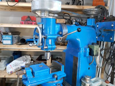
So I've had quirky issues with the clutch on this machine ever since I got it. The worst of the issues is that the clutch assembly rattled when the clutch was disengaged. I've had the clutch apart a few times, a couple just to clean grease off the clutch plate. The driven pulley has a grease zerk to lubricate the bearing. Yes, it is grease, there is even a plate on the back of the lathe saying to grease it at some frequency. I had replaced that bearing originally. PIA to find, paid dearly for a NOS bearing.

Yesterday I had trouble starting the lathe. The VFD frequently faulted out with an over current on acceleration message. I could go in and tweak some VFD parameters, there is a whole slew of 'features' that can be used. And it's not really drawing more current than it should on acceleration if the VFD's current display is to be believed. (Note the LED segments in the above picture are also current draw as reported by the VFD through one of the analog outputs). A little bit of diagnosing and I realized the problem was that the startup was trying to turn the spindle even with the clutch disengaged. The clutch lever is complicated as one direction engages the clutch the opposite direction engages a cone brake on the spindle. I worried something was messed up inside the headstock. My understanding is that isn't easy to dissassemble and reassemble. I've watched a few YouTube videos on people doing that, Maching360 had a good one although I believe that channel has disappeared.

I decided to work the clutch end first. Fix the known quirks.
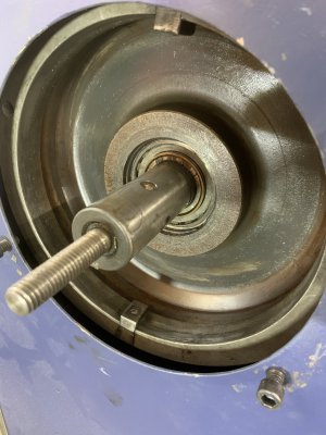
The clutch is basically integrated with the driven pulley, three belts from the motor. Taking the cover off, the exposed end looks like this:
IMG_4222.JPG
The spider assembly is pulled in by center rod til it cams over and holds the clutch engaged. There is a spring loaded pin that registers on the pressure plate ring of holes, that allows the clutch to be adjusted to just enough pressure to cam over and stay locked. The outer arms of the spider press on the pressure plate.

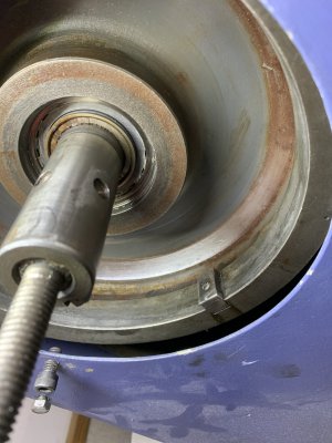
Here's the pressure plate with the spider removed. The first of these two pictures is with the center rod from the clutch lever in the engaged position, the second in the disengaged position. One of the tricks on these clutches is getting the spider on correctly. It threads onto both the center rod and the large diameter thread on the back plate. (The nut on the rod above is redundant, but factory design). The trick is to start the spider threading onto the rod before the center drum. My spider likes 12 full turns onto the rod before starting it threading onto the drum. Otherwise the spring, inside the spider, doesn't have enough pressure to hold the clutch disengaged, and it will drag and spin somewhat.
IMG_4223.JPGIMG_4224.JPG

Here's a picture of the pressure plate coming off. Note that it is held in place only by the spider. The pressure plate has a slot in the inner hole that is engaged by a dog in the back part of the pressure plate (what would be a flywheel in a car?). Note the small bright springs behind this plate. The are often damaged or in part missing on the older monarchs of this design. I had previously replaced these. They help push the outer pressure plate off the clutch disc when it is disengaged.
IMG_4225.JPG

Completely removing the outer pressure plate and the clutch plate, here's the inner pressure plate. It's held onto the center shaft by two set screws, which each have a locking setscrew on top. You can clearly see the dog that engages with the outer pressure plate in this picture. Removing the two setscrews, and the inner pressure plate slides off. The clutch is completely gone, yet I still noticed here that the pressure plate and pulley wanted to rotate together. Trying to figure out what could be dragging, that doesn't make sense for anything in the headstock.
IMG_4227.JPGIMG_4228.JPG

I went ahead and removed the large plate that acts as a belt guard too. Here's a picture of the pulley, belts and motor. You can see the key that the back pressure plate mated with. Also one of the dogs in the pulley that engaged the clutch disc.
IMG_4232.JPG

The drive dogs engage in the clutch disc perimeter. The disc essentially floats on those dogs, nothing else holds the clutch disc. Over the 75+ years of this lathe's life those dogs(keys?) take some abuse. You can see in this picture where they had been hammered away over the years. About 17 thousands of wear. That leaves the clutch disc loose and prone to rattle when disengaged. Obviously when engaged it is clamped between the two pressure plate halves and held pretty well.
IMG_4233.JPG

I wanted to reduce that play so the disc was less likely to rattle when disengaged. Adam Booth (aka Abom79 on YouTube) cut new slots in the perimeter of the clutch disc. I widen mine from .500 to .540, .020 off each side. And then made new dogs/keys that were stepped, .500" in the pulley side, .540 on the clutch disc side, as widening the inside of the pulley would be a more difficult setup.

IMG_4231.JPG

I was test fitting the new dogs in the pulley when it occurred to me that the bearing between the pulley and the center shaft was a likely culprit of my drag problems. Sure enough, spinning the pulley by the belts, I could feel a lot of roughness in that bearing. The bearing that I'd replaced earlier, as mentioned above.

I pulled the pulley, here you can see the end of the bearing. It's a 2 5/8" OD x 1 5/8" ID x 2 3/8" double row needle bearing. I tried to press the bearing out after removing the retaining rings, ended up with a pile of needles. Must have not engaged the outer race of the bearing. The needles don't look very impressive. Here they are after I picked them up off the floor. The chips and debris is from the floor, but most of the needles have rust, and some of them are damaged (look near the bottom). That would explain the rough feeling. I'm guessing the rust must have been included as a NOS feature. The exterior of the bearing when installed look fine.
IMG_4234.JPGIMG_4236.JPG
 

Attachments

  • IMG_4229.JPG
    IMG_4229.JPG
    1.8 MB · Views: 15
  • IMG_4230.JPG
    IMG_4230.JPG
    1.7 MB · Views: 9
Last edited:
Interesting write up and relevant as I have a 61 with what i believe is a similar if not exact clutch. not much forgiveness with needle bearings if not seated just right. Every once in a while I replace an old bearing and find that in time the new one is worse than the old. Usually self inflicted in my case. Dave
 
Clutch Post Mortem
(or my lathe is broke, and I need a lathe to fix it)

So that particular bearing is hard to find. Obviously I need a new one. But I also did some thinking here about why this would fail.
Here's the parts line up:
IMG_4237.JPGIMG_4238.JPGIMG_4239.JPG

Note that I got interrupted above and have not trimmed those keys/dogs to length:
IMG_4241.JPG

Here's the lathe itself, sans clutch and pulley:
IMG_4240.JPG

One problem I have is that the Monarch parts diagrams, while generally pretty good, are very unclear around the clutch. I would guess the clutch, purchased from Edgemont(?), was never drawn out in the typical exploded parts diagram style of the rest of Monarch's diagrams. It is more a picture of the assembly with some arrows to parts call outs.

The bearing is held on the pulley by two retaining rings (one of which went flying off to the dark corners of my shop). The inside of the bearing registers on the flange on the lathe. The outside (clutch side) of the bearing is constrained by the fixed (inner) part of the pressure plate. There is a spacer there (actually hardened) that would seem to keep the inner race captive against the inner pressure plate. But that spacer was also worn out enough that it was loose on the shaft, and definitely rattled horribly. I'm suspicious that rattling and/or wear caused problems with the bearing.

Now I'm left with a problem. My bearing shop couldn't find that bearing originally, and I had ordered the NOS replacement online (locateballbearings.com). I'm a little wary of going that route again. My understanding is that Monarch doesn't have this part and that there is a replacement kit, for $$$.
I'm leaning toward doing a modification myself. One possibility is two needle bearings of the NA4910, 50x72x22 mm. That would require boring out the inside of the pulley about .210" (it is currently 2 5/8 = 66.675mm), and making an inner sleeve since the shaft is 41.275 mm.

I'll need to think about this, and the axial registration. After all, my lathe is now broke, and boring out pulleys and making sleeve sounds like a lathe job. I may have to put my 612 back together without reworking the cross slide.
 
Last edited:
Back
Top