-
Welcome back Guest! Did you know you can mentor other members here at H-M? If not, please check out our Relaunch of Hobby Machinist Mentoring Program!
You are using an out of date browser. It may not display this or other websites correctly.
You should upgrade or use an alternative browser.
You should upgrade or use an alternative browser.
Monarch 612-2516 lathe
- Thread starter rabler
- Start date
- Joined
- Feb 25, 2021
- Messages
- 3,122
Got a replacement part (tumbler) from someone in California parting out a 61. I'm going to have to pull the QCGB off the lathe to actually do the replacement. Good thing I didn't bother putting the apron on yet. Now that the K&T is moved out of the way I can get the gantry over the QCGB to hoist it off, so disassembly can begin. I'll check the angular contact bearings on the various apron shafts while I'm in there, and the bearings on the shaft that holds the tumbler, other than that I'm not going to do a full teardown on the QCGB.
- Joined
- Nov 26, 2017
- Messages
- 1,515
Got a replacement part (tumbler) from someone in California parting out a 61. I'm going to have to pull the QCGB off the lathe to actually do the replacement. Good thing I didn't bother putting the apron on yet. Now that the K&T is moved out of the way I can get the gantry over the QCGB to hoist it off, so disassembly can begin. I'll check the angular contact bearings on the various apron shafts while I'm in there, and the bearings on the shaft that holds the tumbler, other than that I'm not going to do a full teardown on the QCGB.
Wasn't the seller working on trying to get the carriage to move when you picked this unit up? Now we know why it wasn't working.
- Joined
- Feb 25, 2021
- Messages
- 3,122
Close, that problem was a stripped apron nut on the feedrod, clearly at that time the feed rod was turning but the carriage stopped under cutting load. This problem means the feedrod or leadscrew wouldn’t turn at all. Obviously you hope to not see a chain of problems like this, so I’m hoping this is the last issue in getting it operational. But with equipment more than 50 years old there is some degree of gamble with any such purchase, even with a good (expert) inspection. I’ve learned enough to be able to spot worn ways or excessive backlash but I’m still learning.Wasn't the seller working on trying to get the carriage to move when you picked this unit up? Now we know why it wasn't working.
Last edited:
- Joined
- Feb 25, 2021
- Messages
- 3,122
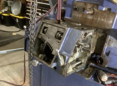
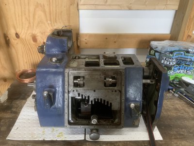
Finally got this monster of a QCGB off. Turned into a hassle. Two shafts go under the headstock from the qcgb, one is for the clutch, the other is for the rapid traverse. They both are keyed off a coupling that should just slide off, but the clutch rod was bound up and took a lot of persuasion. Now I need to get the tumbler out, some disassembly required.


- Joined
- Nov 24, 2014
- Messages
- 3,152
I'm curious what you think was the cause of the clutch shaft being so hard to separate?
A picture is worth . . .
Those sorts of details are helpful to teach us pilgrims what to look for if ever venturing into similar territory.
A picture is worth . . .
Those sorts of details are helpful to teach us pilgrims what to look for if ever venturing into similar territory.
- Joined
- Feb 25, 2021
- Messages
- 3,122
Several things made it complicated.I'm curious what you think was the cause of the clutch shaft being so hard to separate?
A picture is worth . . .
Those sorts of details are helpful to teach us pilgrims what to look for if ever venturing into similar territory.
One is that it is just a huge gearbox, maybe 400lbs or more. So maneuvering it requires a hoist/crane. My gantry crane is big (I used it to pick up the entire lathe, at least 8000 lbs worth). Space is limited. Finding a place to connect the hoist so that the gearbox lifts without twisting or rolling took lots of fooling around.
Two is that I haven’t removed this gearbox before. No instructions beyond some exploded parts diagrams. So lots of guessing involved. I knew all the apron shafts had to come out. There is also a plate on the gearbox that faces the apron holding the end of all those shafts. Apron shafts off first. Tried to take that plate off, but as I feared it has capscrews that aren’t accessible until the gearbox is pulled forwrd a few inches.
The gearbox wraps around the left side if the headstock, so pulling forward seems obvious. But the gearbox needs to be lifted up 1/2” to clear a lip going forward. That lip acts as an oilpan under the gearbox.
Going forward causes the left side wrap around to catch on a shaft stub for the banjo gears going from the headstock to the gearbox, wgich requires going left.
The shafts should slide out of the couplings if the gearbox goes straight forward away from the headstock. But between not knowing the issues and procedures, I was sort of trying random things.
Rather than getting too aggravated I worked on this a bit at a time, over about a week.
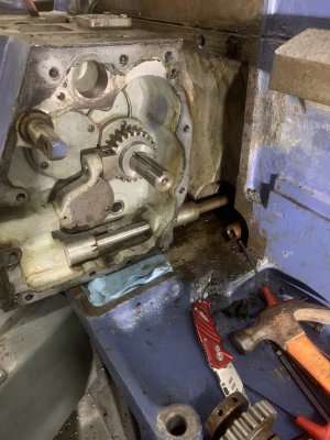
Monarch likes to build things to tight tolerances. There is basically a stub shaft coming out of the back of the gearbox, into a coupling, which joins to a longer shaft going under the headstock. That coupling has a roll pin connecting it to the longer shaft. A 5lb hammer would not drive that rollpin out. It is a bit beat up. And the coupling is also under some torque/tension from earlier attempts. So lots of attempts to tap out that roll pin failed. Turns out roll pins are also pretty hard. It wouldn’t drill out. Both drilling and tapping in limited space, a few inches between the gearbox and headstock. My concern was bending one of those shafts, or damaging bearings by tapping too hard.
So, lots of little things on top of the huge mass of this beast.
The offending coupling shows up on the right lower side of the gearbox here. The end of other coupling from the rapids can just be seen.

Last edited:
- Joined
- Nov 24, 2014
- Messages
- 3,152
When you say "roll pin", is that a "C" cross section (McMaster calls them "Slotted Spring Pins") or the wound spiral sheet metal type
(McMaster calls them "Coiled Spring Pins")?
Thanks so much for the excellent explanation. It really adds to the education value, for me anyway.
It sounds like a heavy (dangerous) Chinese Puzzle solution, then to find an uncooperative pin.
PS: I recently disassembled (for thorough cleaning) a piece of tooling that used a pin in a way I hadn't seen before.
I took a good look, before pounding, because I didn't know what type of pin it was going to be. I didn't want to be pounding on the fat end of a taper pin. It didn't seem to be a taper pin. I thought a 3/32" pin punch would do it but a couple of appropriate raps didn't get me very far. I switched to 1/16" pin punch and Voilà.
The hole (about 1/16" diameter) was through the part and countersunk (about 1/8" diameter) at both external surfaces.
The pin is soft steel (about 1/16" diameter) and was lightly peened into the countersinks on both ends to retain.
- Joined
- Nov 26, 2017
- Messages
- 1,515
It is always fun to break down a piece of equipment that 1) you are not familiar with, 2) have no manual, 3) and have limited information available.
You seem to have the right mind set. When doing this kind of work it is so easy to overlook a connection, obstacle, etc and because of the weight of the pieces, cause serious damage to a component(s). Taking your time and reviewing the situation multiple times is the way to go. Getting in a hurry will only serve to complicate the project. I am sure over that week, even though you were not face to face with the lathe, you were thinking through different scenarios and options.
Nice work in getting that apart.
- Joined
- Jan 10, 2019
- Messages
- 1,042
A question, how did you support that beast when lifting it. In the one picture, it's doesn't look like it was supported at the time.
Your project reminds me of the local antique tractor association. Part of the deal is that you join and "adopt" one of the sad old lumps, restoring into like-new condition. Your situation is like what I heard someone there saying about adopting a bulldozer, "It was fun restoring it, but it's a real pain because every single part coming off it required a hoist of some sort."
Your project reminds me of the local antique tractor association. Part of the deal is that you join and "adopt" one of the sad old lumps, restoring into like-new condition. Your situation is like what I heard someone there saying about adopting a bulldozer, "It was fun restoring it, but it's a real pain because every single part coming off it required a hoist of some sort."

