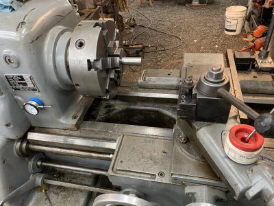
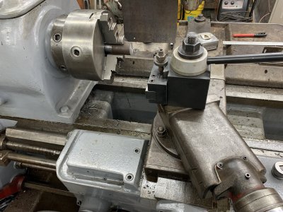
So here’s some pics of the CA tool post on my latheAloris CA post next to the original 4 way toolpost. The CA looks a little small on the compound, I'll need to raise it just under 1/4" for 1/2" tools to reach centerline.
View attachment 375135View attachment 375136

-
Welcome back Guest! Did you know you can mentor other members here at H-M? If not, please check out our Relaunch of Hobby Machinist Mentoring Program!
You are using an out of date browser. It may not display this or other websites correctly.
You should upgrade or use an alternative browser.
You should upgrade or use an alternative browser.
Monarch 612-2516 lathe
- Thread starter rabler
- Start date
- Joined
- Feb 25, 2021
- Messages
- 3,119
Today I put quite a bit of time in working on the apron on this thing. One of the things I noticed was that I could not move the halfnut lever very far. Nor were the half nuts moving through a range I thought reasonable, only about 3/16". I was at first suspicious of the interlock with the feed rod engagement. I took that off. Still no movement range.

So I took the whole half nut mechanism apart. The plate with the short diagonal slot near the middle of the above picture gave me some grief as it was pinned as well as bolted and the pins were tight, hard to get out. Finally got the whole half nut mechanism out.

Lever still didn't move. The pins should at least turn through 90 degrees. Turns out the front lever goes through a bevel gear. If you look very carefully you can see the top the roll pin that holds the bevel gear onto the shaft, sticking out of the bevel gear just a bit. That was enough to interfere in the lever block. I ground the pin down just a bit (it was too mushroomed to drive in)), and problem solved.

If you look at the first picture above you can see a copper line near the top center of the picture. It goes from the half nut to the brass gear that engages with the worm gear on the feed rod. You can also see a very short piece of copper tube and a brass connector just above the half nut. The tube above the half nut feeds oil into the half nut when the half nut is closed, and when the half nut is fully open feeds the oil through the upper center tube to the brass driven gear off the feed rod worm. So it is important on this lathe to make sure the half nut is fully open when using the feed mechanism to lubricate the worm and gear.
After getting that all back together, I struggled to get the apron back under the carriage. Easier said than done. The apron weighs enough that it needs to be hoisted into place. Problem was I had put the K&T mill 6" too close to the lathe, so I could no longer get the hoist around the back of the lathe. So I had started the day by jacking up the K&T, (which weighs almost as much as this lathe), putting it on skates, and prying it over the needed 6". Getting a lifting point that would clear the carriage while hoisting the apron, plus would reasonably balance the apron, was a real challenge. Took several attempts and a lot of 'creative grumbling'.

Anyway, got the apron attached and the 8 bolts through the top of the carriage tightened. Then had to figure out the clutch rod. On the QCGB end it has a taper pin through two bushings and the shaft. Of course a taper pin only goes through those properly one way or it won't seat fully. The clutch rod goes through the apron, and has two levers, one at the right hand side of the apron and one at the right hand side of the QCGB. I barely had enough room between the wall and the tailstock end of the lathe to get the rod into the right side of the apron and slide it over. Then had to try a couple times to get everything clocked right. So that's in. Just need to get the feed rod, rapid traverse drive rod, and the leadscrew in.
Then I realized that I had put the apron on, but the carriage lock (which sits inside the apron above the halfnut on this lathe), was still in the parts box. A lot more 'creative grumbling' ensued.
I'll take a more careful look at it tomorrow and see if it is going to be possible to get the carriage lock in without pulling the apron back out, but I'm not optimistic. Oh well.
All in all, it felt good to get some time back in the shop, even with the various issues.
So I took the whole half nut mechanism apart. The plate with the short diagonal slot near the middle of the above picture gave me some grief as it was pinned as well as bolted and the pins were tight, hard to get out. Finally got the whole half nut mechanism out.
Lever still didn't move. The pins should at least turn through 90 degrees. Turns out the front lever goes through a bevel gear. If you look very carefully you can see the top the roll pin that holds the bevel gear onto the shaft, sticking out of the bevel gear just a bit. That was enough to interfere in the lever block. I ground the pin down just a bit (it was too mushroomed to drive in)), and problem solved.
If you look at the first picture above you can see a copper line near the top center of the picture. It goes from the half nut to the brass gear that engages with the worm gear on the feed rod. You can also see a very short piece of copper tube and a brass connector just above the half nut. The tube above the half nut feeds oil into the half nut when the half nut is closed, and when the half nut is fully open feeds the oil through the upper center tube to the brass driven gear off the feed rod worm. So it is important on this lathe to make sure the half nut is fully open when using the feed mechanism to lubricate the worm and gear.
After getting that all back together, I struggled to get the apron back under the carriage. Easier said than done. The apron weighs enough that it needs to be hoisted into place. Problem was I had put the K&T mill 6" too close to the lathe, so I could no longer get the hoist around the back of the lathe. So I had started the day by jacking up the K&T, (which weighs almost as much as this lathe), putting it on skates, and prying it over the needed 6". Getting a lifting point that would clear the carriage while hoisting the apron, plus would reasonably balance the apron, was a real challenge. Took several attempts and a lot of 'creative grumbling'.
Anyway, got the apron attached and the 8 bolts through the top of the carriage tightened. Then had to figure out the clutch rod. On the QCGB end it has a taper pin through two bushings and the shaft. Of course a taper pin only goes through those properly one way or it won't seat fully. The clutch rod goes through the apron, and has two levers, one at the right hand side of the apron and one at the right hand side of the QCGB. I barely had enough room between the wall and the tailstock end of the lathe to get the rod into the right side of the apron and slide it over. Then had to try a couple times to get everything clocked right. So that's in. Just need to get the feed rod, rapid traverse drive rod, and the leadscrew in.
Then I realized that I had put the apron on, but the carriage lock (which sits inside the apron above the halfnut on this lathe), was still in the parts box. A lot more 'creative grumbling' ensued.
I'll take a more careful look at it tomorrow and see if it is going to be possible to get the carriage lock in without pulling the apron back out, but I'm not optimistic. Oh well.
All in all, it felt good to get some time back in the shop, even with the various issues.
Last edited:
- Joined
- Feb 25, 2021
- Messages
- 3,119
I have a 4’ spreader bar that I should have used today. I’m sure that’ll come into play if it needs to come off again. If so I’ll get pics.Excellent progress there.
If you have todropdismount the apron again, I'd like to see the lifting jig.
- Joined
- Feb 25, 2021
- Messages
- 3,119
Fortunately it went fairly easy, I only needed to drop the apron down about 4" to get the carriage lock under there. The dirt marks on the bottom of the apron are from me using my foot (while seated in a chair) to push the bottom of the apron into place while putting the cap screws in from the top. I got the feed rod and rapid traverse rod started through the apron. Took a break for lunch.I have a 4’ spreader bar that I should have used today. I’m sure that’ll come into play if it needs to come off again. If so I’ll get pics.

- Joined
- Nov 26, 2017
- Messages
- 1,515
We use what we have. Looking like a lathe again.
- Joined
- Feb 25, 2021
- Messages
- 3,119
So I picked this lathe up almost a year ago. Here is a rough cost break down to date:
Lathe $2300
Fuel & Hotel $300
Replace main motor w/ 10HP, use original 20HP with WNY panel to build RPC: $1000 (used across three machines)
New Aloris CA toolpost with a couple holders $1000
Paint and cleaning supplies: $300
QCGB replacement tumbler: $100
Oil: $120
Wiring, conduit, and overload relay replacements: $200
Planned:
Bison 16" 4-jaw: $2000
DRO: $1000
$8320 Total
No steady or follow rest. Obviously no cutting tools and only a few holders. I'll eventually want to fab a small jib crane over it. That's about $4300 for getting the lathe working, and another $4000 for chuck, DRO, and toolpost. Looking forward, I can see sinking about $2000 into inserts, tools, and toolholders.
Last edited:
Now that’s the one thing I don’t have yet on my lathe is a good working DRO !!! And want to get at some point I have a DRO Pros one on my Bridgeport mill and there’s a old Anilam on my VanNorman mill but it works !!!Thinking about another Electronica 400 DRO for this lathe, I have one on my CK and like it.
- Joined
- Feb 25, 2021
- Messages
- 3,119
Today's challenge was putting the leadscrew back on.
The leadscrew itself is about 1.5" in diameter, and over 8' long end to end. Weighs maybe 60-70 lbs. Pretty big in my book.
The first challenge was that I had set the lathe so the tailstock end was about 2' from a wall. With the carriage cranked far left toward the headstock, there wasn't enough room to get the leadscrew into the right side of the apron. So out came the toe jack, and the skates, jacked it up and onto three skates, then used the tractor to push it over the needed extra foot.
Had to take the threading dial off to insert the leadscrew. The headstock end of the leadscrew isn't threaded and is full diameter so the gear for the threading dial blocked sliding the leadscrew in. Three capscrews and that came off and the leadscrew slid through the apron easily enough with the half nuts open.
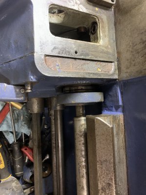
Then things got complicated. Trying to get the leadscrew connected to the QCGB turned out to be quite complicated. Here's what the end of the leadscrew looks like (there is a vertical oil glass in the background that is not part of the leadscrew): The leadscrew as pictured has
1) a round nut, fine threaded
2) gear held on with a woodruff key.
3) roller bearing
4) spacer
5) tapered bearing and cone
6) oil ring spacer with felt oil wick
7) tapered bearing and cone
8) cover plate
9) some wort of big flanged bushing in the QCGB endplate

Here's the full up parts diagram description of the end plate and the leadscrew end assembly (shaft B), the leadscrew itself appears on a different sheet.

I was hoping the parts diagram would at least show which way the taper bearings sit, but no luck there. Dealing with parts Q29-Q39. Taking the leadscrew out had been a matter of removing the nut (Q29), pulling the shaft out a few inches, pulling the gear off the end (Q30), and then pulling the leadscrew out. Just reverse to re-install, right? I could only wish!
The challenge is that there isn't a lot of room where that gear sits. The gear has a bit of a flange on the right side. The trick is getting the woodruff key in. Easy enough to get the gear on the shaft, slide the shaft over a bit, and get the nut on there without getting the woodruff key in. Of course, without the woodruff key, the leadscrew is worthless. But there wasn't enough room to get the woodruff key between the gear and the right side. Begin lots of loud 'creative grumbling'. Especially since anything that dropped went deep into this cavity and we needed a magnet to fish things out. Fortunately my wife was helping me with this today. Lots of trips between the garage and the workshop by the house (about 1/4 mile), she got plenty of walking in.

If you look carefully at the above picture you can see a barrel to the right of the gear, around the shaft. This is Q36. After some head scratching and several attempts to get the woodruff key in that resulted in fishing various parts out of the bottom with a magnet, I realized Q36 needed to be driven to the right a bit which would give enough room to get the woodruff key in there.

So, an afternoon's work got the leadscrew back in. Put the support bracket for the leadscrew, clutch rod, feed rod, and traverse rod on the tailstock end of the bed. Used the tractor to pull the lathe back into the previous position. Fired it up and tested it. Whooo-hooo, everything worked. Rapid traverse for the carriage left/right, cross slide in/out. Feed rod. Leadscrew.
I would say that the rapid traverse is neat but is going to take some caution. The levers on the apron activate it, but while rapidly traversing, the corresponding dial/crank turns fairly rapidly. I would not want to get any body parts caught in those cranks. They sit at an awkward height that could easily zipper out of your pants, and anything else they happen to ... catch.
I'm going to do some test cuts with it for fun in the next couple days, but it isn't done yet. I'll want to dissassemble the cross slide as it is fairly stiff. Quick tinkering with the gib adjustment didn't make a difference.
The leadscrew itself is about 1.5" in diameter, and over 8' long end to end. Weighs maybe 60-70 lbs. Pretty big in my book.
The first challenge was that I had set the lathe so the tailstock end was about 2' from a wall. With the carriage cranked far left toward the headstock, there wasn't enough room to get the leadscrew into the right side of the apron. So out came the toe jack, and the skates, jacked it up and onto three skates, then used the tractor to push it over the needed extra foot.
Had to take the threading dial off to insert the leadscrew. The headstock end of the leadscrew isn't threaded and is full diameter so the gear for the threading dial blocked sliding the leadscrew in. Three capscrews and that came off and the leadscrew slid through the apron easily enough with the half nuts open.
Then things got complicated. Trying to get the leadscrew connected to the QCGB turned out to be quite complicated. Here's what the end of the leadscrew looks like (there is a vertical oil glass in the background that is not part of the leadscrew): The leadscrew as pictured has
1) a round nut, fine threaded
2) gear held on with a woodruff key.
3) roller bearing
4) spacer
5) tapered bearing and cone
6) oil ring spacer with felt oil wick
7) tapered bearing and cone
8) cover plate
9) some wort of big flanged bushing in the QCGB endplate
Here's the full up parts diagram description of the end plate and the leadscrew end assembly (shaft B), the leadscrew itself appears on a different sheet.
I was hoping the parts diagram would at least show which way the taper bearings sit, but no luck there. Dealing with parts Q29-Q39. Taking the leadscrew out had been a matter of removing the nut (Q29), pulling the shaft out a few inches, pulling the gear off the end (Q30), and then pulling the leadscrew out. Just reverse to re-install, right? I could only wish!
The challenge is that there isn't a lot of room where that gear sits. The gear has a bit of a flange on the right side. The trick is getting the woodruff key in. Easy enough to get the gear on the shaft, slide the shaft over a bit, and get the nut on there without getting the woodruff key in. Of course, without the woodruff key, the leadscrew is worthless. But there wasn't enough room to get the woodruff key between the gear and the right side. Begin lots of loud 'creative grumbling'. Especially since anything that dropped went deep into this cavity and we needed a magnet to fish things out. Fortunately my wife was helping me with this today. Lots of trips between the garage and the workshop by the house (about 1/4 mile), she got plenty of walking in.
If you look carefully at the above picture you can see a barrel to the right of the gear, around the shaft. This is Q36. After some head scratching and several attempts to get the woodruff key in that resulted in fishing various parts out of the bottom with a magnet, I realized Q36 needed to be driven to the right a bit which would give enough room to get the woodruff key in there.
So, an afternoon's work got the leadscrew back in. Put the support bracket for the leadscrew, clutch rod, feed rod, and traverse rod on the tailstock end of the bed. Used the tractor to pull the lathe back into the previous position. Fired it up and tested it. Whooo-hooo, everything worked. Rapid traverse for the carriage left/right, cross slide in/out. Feed rod. Leadscrew.
I would say that the rapid traverse is neat but is going to take some caution. The levers on the apron activate it, but while rapidly traversing, the corresponding dial/crank turns fairly rapidly. I would not want to get any body parts caught in those cranks. They sit at an awkward height that could easily zipper out of your pants, and anything else they happen to ... catch.
I'm going to do some test cuts with it for fun in the next couple days, but it isn't done yet. I'll want to dissassemble the cross slide as it is fairly stiff. Quick tinkering with the gib adjustment didn't make a difference.