Monarch 612-2516 lathe

Been ordering some tooling. Lots of 1" shank holders:
A neutral MSDN
L & R MCLN
L & R MWLN
For now ordering holders for smaller 3/8 inscribed circle inserts to match my tooling for the other lathes. Otherwise the necessary collection of inserts could quickly get out of hand. I may at some point pick up a couple holders for 1/2" or larger inserts for roughing, but I'm rarely pressed to move large amounts of metal quickly even if this lathe would happily oblige.

Now I just need to finish my diamond lapper so I can make some monster HSS tooling.
 
Well, I may have gotten carried away, but this lathe is in another building, about 1/4 mile away from my other machines. So I can't easily share tools between machines. So I went ahead and purchased quite a bit of tooling for this machine.

The QCTP pictured is an Aloris CA, with a 1" Kennametal MCLNR tool. Next to it is the original 4-way toolpost with a Shars 1 1/4" MCLNR insert tool for scale. In front of the Aloris QCTP is the original shaft that came with the shaft, and a longer shaft I made for it. I'm milling a new T-nut and spacer plate to raise the QCTP up by .2" so that even 1/2" insert holders will work in this toolpost. Also a couple of MT4 dead centers for the tailstock. The tailstock on this machine has bearings in it so live centers aren't needed. That does require a missing special adapter to use drills or reamers in the tailstock. I'll probably use the toolpost/carriage for most of those operations.

The chuck wrench is something I made this week to go with this lathe.

Anyway, this lathe is now more or less functional. Not that it is *finished*. I expect to iterate. But I'm going to shift to working on improving the CK and use this lathe to see what further work suits me.
IMG_4073.JPG
 
Last edited:
@rabler

I'd never heard of a tailstock spindle with taper supported by integral bearings. Is that a factory set-up or shop modification?
I'd like to see more details if you get a chance.

Such a configuration only makes sense to me if the tailstock is intended to never be used for drilling or tapping. I guess I'm just used to the conventional configuration (non-rotating taper). Do you have an image of the "missing special adaptor"?
Factory option, called an anti-friction tailstock. See parts manual from vintagemachinery.org. Its not an exact match to my model year but best I have.
 
That's a pretty cool feature. Gives you a live, dead center, or I suppose you could call it a "Zombie center". :grin: Mike
 
That's a pretty cool feature. Gives you a live, dead center, or I suppose you could call it a "Zombie center". :grin: Mike
LOL. Does that mean instead of a tailstock I should call it a tombstone?

It certainly is heavy enough to be a tombstone. It must weigh at least 300 lbs, heavy enough that even with the ways well oiled the only way to slide it is to stand down at the tailstock end and use your body weight to push/pull. It is suppose to have a handle and gear that engage with the carriage rack to move it but that part is missing.

I was about to say, that is why they have a handle and it is gear driven, but you indicated it was missing. Hopefully you can find a replacement. Would make using the lathe much easier.

I am so envious of that lathe. Hope when we get into our final home, that I am able to find one for my shop. Congrats. Loved watching you go through it. Appreciate your meticulous process and attention to detail.
Thanks much. I’ll probably make a handle and arm for the tailstock as a weldment, if I can find the appropriate gear.
 
An interesting project that stretched my skills a bit. This was a combination of welding and machining. I've heard that called a weldment.

One of the things that didn't come with this lathe that is relatively critical is a drive crank for the tailstock. The tailstock on this thing is truly massive. Even with well oiled ways, it's all I can do to slide the thing along the ways. Doing that requires standing at tailstock end of the bed and throwing my considerable body weight into it. The lathe is designed to have a hand crank that engages with the carriage rack to allow some mechanical advantage to move the tailstock. You can see the four holes (two bolt holes and two locating pins) on the side of the tailstock in this picture. Note the size of the tailstock relative to the one gallon paint can.
IMG_4060c.jpg

The crank needs to go over the V-way for the carriage and over the leadscrew (which is not installed in the above picture). I wanted a somewhat cosmetically pleasing design.

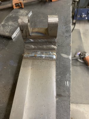
I started with some hot-rolled 1" x 3" bar stock, and face-milled off the mill scale. I cut four pieces. The first piece being a U-shaped piece with holes for a hinge pin, then two short pieces, and then a long tail piece. All four pieces had a 22.5* taper cut on the adjoining faces, and then those faces V'd out on both sides for weld beads. Welded that all up with the MIG welder.

IMG_4155.JPG

Unfortunately despite my best efforts the hinge pin was a few degrees off from being 90* from the tail piece. I decided to taper the tail piece going down to give it a little more style, although it was really a fix for that problem. Ended up looking good so I'm pleased.

After a little work with an angle grinder, I had a decent looking piece.
IMG_4157.JPG

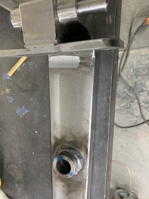
Then I milled up the plate to go onto the tailstock, and the pivot block. The plate is faced 3/8" HRS, with a 1.5" x 1.5" x 2" block on the center. I had milled a 3/4" hole centered under the block, clamped it up and plug welded it to the block before welding the perimeter. I milled the weld off on the top. Here you can see the two together with the hinge pin partially installed.
IMG_4159.JPG

Next step was to make the through-hole for the shaft for the crank. Getting the location correct was a bit of a challenge. I fit the piece up onto the tailstock and used a 1-2-3 off the bottom of the rack to mark the location of the rack teeth, and then worked from there. Unfortunately I don't have a picture of that setup. But that gave me a location to drill for the shaft. I purchased a gear from McMaster, 8 DP 12 tooth 20* PA. Pricey, but I have yet to try gear cutting. My rotary table has way too much backlash in the worm, I'll need to work on that before using it for something like that. That gear has a 3/4" bore for a shaft. I started by drilling a 7/8" hole, and a 7/8" hole in a 1.50" diameter bushing to increase the contact area for the shaft. I also turned a 7/8" plug to drop through both to keep them in line while welding them together.
IMG_4160.JPG

Once welded together, cut the piece to lenth around the hole using the horizontal bandsaw, then used the boring head on the mill to open the combined hole up to 1.0", giving me a perfectly concentric through hole. I then used the rotary table (no picture) to round off the bottom bandsaw cuts.
IMG_4164.JPG

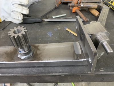
I turned a 1.001" OD, .753" ID bronze bushing, put the bushing in the freezer and the large piece in the shop toaster oven, and pressed them together for a good solid fit. Here's a test fit: This uses a scrap piece I turned for the gear shaft. Plan is to turn a longer shaft with a 7/8" hex end coupling protruding. That happens to also be the size of the carriage lock bolt on this lathe so I can use the crank to also lock the carriage.
IMG_4165.JPG

Still need to make that shaft, and the handcrank, and then paint everything. Also waiting for some slight shorter 1/2" SHCS as the ones pictured above are too long to seat in the blind holes in the tailstock.
 

Attachments

  • IMG_4156.JPG
    IMG_4156.JPG
    1.3 MB · Views: 8
  • IMG_4161.JPG
    IMG_4161.JPG
    1.1 MB · Views: 7
  • IMG_4162.JPG
    IMG_4162.JPG
    2.6 MB · Views: 7
Last edited:
Back
Top