- Joined
- Sep 5, 2013
- Messages
- 3,207
My foray into gear cutting continues although this is really the reason I embarked on it in the first place — a set of change gears.
I had already figured out how do the double keyway and that had worked fine, and the cutting of the gears themselves was going equally well until about two-thirds of the way through the set. Then I discovered, of all things, that I didn’t have enough travel in the knee to cut the last three large sizes of gear!
I was (and still am) a bit dumbfounded as to how this could be, the gears are not that large. But regardless of whichever way I held my tongue I still could not get the mill table down far enough to obtain the proper tooth depth. Hmmm....
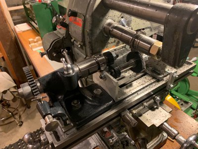
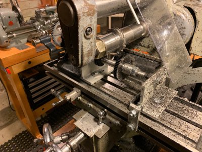
After much head scratching I came up with the plan to make a secondary pair of indexing centres with a lower centre height and move the gear cutting arbour further away from the cutter arbour on the machine. In order to keep the indexing feature of my original centres, I could drive this auxiliary pair of centres off the first pair with, what else, a pair of gears. So that’s what I did.
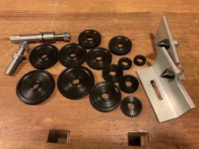
I turned two 60-degree centre points out of some 4140, hardened them over a propane torch, and supported them on a couple pieces of aluminum angle I had kicking around. Then made up two matching 32T acetal gears: one to press onto the end of the gear blank arbour and be the “driven” gear; the second or “driver” gear would mount on a stub arbour held in an ER collet that I could mount to the original indexing snout. It really helped that the 1”-10 thread on the indexing centre is the same as my lathe spindle which is also the same as the mill spindle so I already had a collet chuck and collets I could use. A second stub arbour was nothing fancy and easily done.

All in all it took about four times as long to build and figure all the new parts than it did to cut the entire set of gears, but isn’t that always the way. The setup does work, fairly well actually, although I can see areas to improve on. The mesh between the two driving gears is critical for accurate tooth spacing, and any amount of play can introduce a slight variance. For my purposes here I don’t think it’s significant, but if it were for a tighter expectation I’d want to revisit that part.

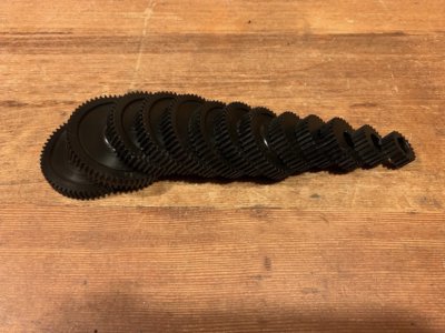
The gears themselves turned out fine. This set is kind of experimental anyway being out of Acetron, and I’m not sure how durable they’ll be. But it was a fun exercise that’s for sure, and I have a few new tricks in the bag for next time.


Thanks for looking.
-frank
I had already figured out how do the double keyway and that had worked fine, and the cutting of the gears themselves was going equally well until about two-thirds of the way through the set. Then I discovered, of all things, that I didn’t have enough travel in the knee to cut the last three large sizes of gear!
I was (and still am) a bit dumbfounded as to how this could be, the gears are not that large. But regardless of whichever way I held my tongue I still could not get the mill table down far enough to obtain the proper tooth depth. Hmmm....
After much head scratching I came up with the plan to make a secondary pair of indexing centres with a lower centre height and move the gear cutting arbour further away from the cutter arbour on the machine. In order to keep the indexing feature of my original centres, I could drive this auxiliary pair of centres off the first pair with, what else, a pair of gears. So that’s what I did.
I turned two 60-degree centre points out of some 4140, hardened them over a propane torch, and supported them on a couple pieces of aluminum angle I had kicking around. Then made up two matching 32T acetal gears: one to press onto the end of the gear blank arbour and be the “driven” gear; the second or “driver” gear would mount on a stub arbour held in an ER collet that I could mount to the original indexing snout. It really helped that the 1”-10 thread on the indexing centre is the same as my lathe spindle which is also the same as the mill spindle so I already had a collet chuck and collets I could use. A second stub arbour was nothing fancy and easily done.

All in all it took about four times as long to build and figure all the new parts than it did to cut the entire set of gears, but isn’t that always the way. The setup does work, fairly well actually, although I can see areas to improve on. The mesh between the two driving gears is critical for accurate tooth spacing, and any amount of play can introduce a slight variance. For my purposes here I don’t think it’s significant, but if it were for a tighter expectation I’d want to revisit that part.

The gears themselves turned out fine. This set is kind of experimental anyway being out of Acetron, and I’m not sure how durable they’ll be. But it was a fun exercise that’s for sure, and I have a few new tricks in the bag for next time.


Thanks for looking.
-frank


