New Chip Guard
Milling machines are very messy, of course. I got tired of the smallest cutting operation getting chips all over the floor, so I decided to make a
larger chip shield to start with. First, I made a bracket to hold the back of the new shield much higher, especially because I have decided to leave
my swivel base under the vise at all times if possible so that it is always available.
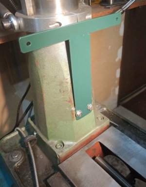
I gave a lot of thought to what material to use for the new shield, and the best I came up with for the moment was a piece of 1/8" thick x 3 feet wide
Neoprene sheeting. Should be ok and it was cheap. I wanted the top edge to have a finished look and to be fairly strong. I don't have access to a
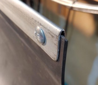
sheet metal brake that big so here is what I did: I took a length of 3/4" thinwall electrical conduit and began to flatten it between two plates in my
press, not doing too much at a time to minimize dents. After it became quite oval, I put a piece of 1/8" flat bar inside it so that I could then press
it down flatter and maintain the space inside. I clamped a piece of metal to the little table of my horizontal band saw (with it standing up) for a
rip fence and cut off one curved edge of the conduit. I drilled holes and filed them square to fit some 1/4" carriage bolts. I placed the conduit over
the edge of the Neoprene and marked the hole positions, then I took it off and made holes in the rubber with a hollow punch.
Next, I made two strips of flat stock to attach the bottom of the shield to the machine base below the table. I used 1" wide for the side toward the
table so it wouldn't rub and the other strip 1.5" wide so it would help influence the Neoprene to take the shape I wanted.
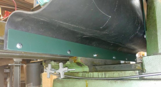
When I put the table all the way back, the soft rubber didn't hold the shape I wanted for a valley, so I added a strip across the lower bracket bolts to influence the shape I desired.
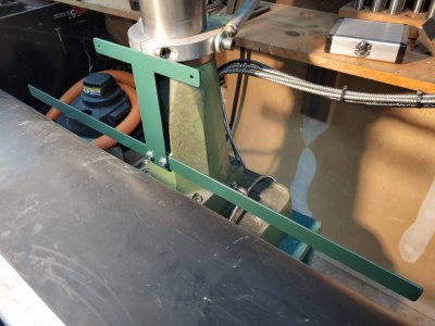
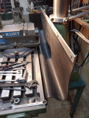
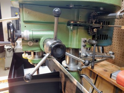
So far, so good. Then I found that when the head is lowered pretty far, the top of the shield now interfered with the quill handles. I decided to shorten the handles for more clearance and still can remove one or more if a particular operation requires it. I chopped 2" off of each handle. I ran into something unexpected when I was going to rethread the ends in the lathe: even though the mill was made in Taiwan, most or all of the thread are imperial. The ends of the handles had looked like 1/2-13 by eye but I decided to be more careful than I usually am and checked the original threads with a thread pitch gage. None of the metric gages matched up, and the exact imperial gage was 12 TPI. One of my threading charts showed 1/2-12 as a special thread size, and not just for Whitworth. I cut the threads and they fit just right.
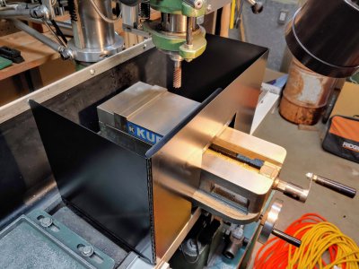
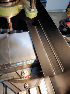
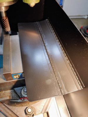
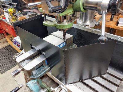
Next I needed more guards to direct the chips onto the table and into the valley of the wide chip guard. I designed this folding steel shield to fit many situations, again as a first attempt. I knew I wanted to use some piano hinges but aesthetics are important to me so I didn't want some big, clunky ones attached with screws of rivets. The only place I found what I wanted was McMaster Carr where the shipping costs more than the item you need. I ordered two 3 foot sections of unplated steel hinge, 3/4" wide when opened. I got to use my spot welder to weld them on with one-inch spacing between each weld. I cut the center plate to fit over the swivel base and the vise, making the opening high enough to clear the movable jaw when it is moved back and then added a a couple of wide plates to cover the top opening whether the jaw is closed or open. The bottom edges of the side plates have plastic edge protectors and the center plate has "feet" folded under with rubber pads to rest on the shield over the DRO scale. Haven't really tested it yet (it's so cold in the garage!) but I think it will work well.
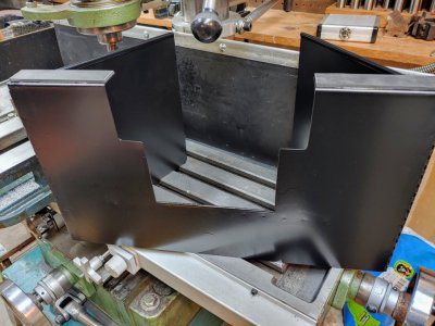
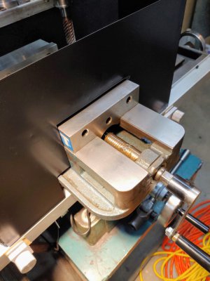
Now it gets really crazy!
If you have seen my other posts you will have seen the guide I made to keep the head aligned and that I motorized the lifting of the head as well, plus the extra-long nuts I made to make it easier to put a wrench on them. These things combined make it so easy to change the head height that I don't even give it a thought in planning ahead on operations. But still, there were TWO nuts to loosen and tighten each time and I wanted it to be even easier. This is what I did: I had some .500" pitch roller chain so I ordered a couple of 14-tooth sprockets with 3/4" bores from Amazon. I bored the holes out to 7/8" which pretty much removed the keyways but I planned to weld them on anyway. I shortened one of my long nuts and turned a section to 7/8" round for the sprocket. I welded on the sprocket and then faced off the combination. I actually had to lengthen the other nut to get it out where I wanted it. I turned a round section on it as well but just put the sprocket on it with a setscrew.
The original 5/8" bolts were a very loose fit in the holes through the head and I needed a consistent action so I made new bolts to fit with minimum clearance. Also, the hex recesses cast into the head were much bigger than the existing bolt holes so I made close-fitting bolt heads to weld to my new bolts. The spacing of the bolts holes in the head was not a multiple of .500" as I hoped, but fairly close. I got the bright idea of turning the 5/8" threads on my new bolts offset from the center so the outside of the thread was tangent to the outside of the oversize-diameter bolt at one point. Then I figured I could just rotate the bolts until the slack was taken out of the chain and then mark them for the orientation of the bolt heads to weld on. More math would have helped me here. It worked to a degree but not quite enough. I realize now that I could have turned the threads a but further off center and just sacrificed part of the outside threads to get more movement, it would have been strong enough. I didn't want to remake them, it was close enough.
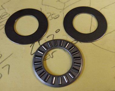
So, with the bolts postioned, I welded on the heads. I needed all of this to stay as repeatable as possible and the cast surface of the head is not that flat or even square to the bolt hole. I installed Torrington bearings (flat roller bearings with hardened washers) to make the clamping nuts easier to tighten and eliminate wear that would change the timing of the sprockets.
Then I put both of the nut/sprocket assemblies on and tightened them to 35 foot pounds which seemed good to me, a retired auto tech. This way I could mark them to keep them synchronized when tightened. I put on the chain and took the slack out of the back of it by loosening the setscrew in the upper sprocket. I still wanted to be able to fine-tune this part so I turned the sprocket slightly counter-clockwise before I welded it on. This way I could face off small amounts of the upper nut to bring it into perfect timing. Here is the finished product (also shows my tool-free belt tensioner that I don't use any longer since I put on the 3-phase motor and VFD)
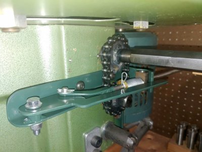
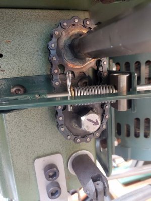
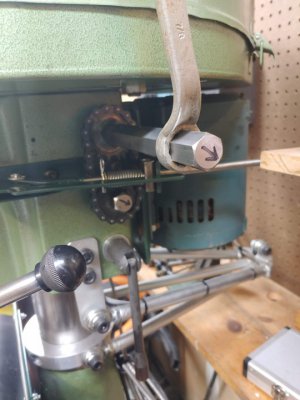
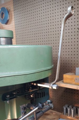
I think it worked out quite well. If I want to change the head height now, all I do is pull the wrench about a half-turn, hit the toggle switch to move the head, and give the wrench a stout shove back up and it's ready to go.
About the only thing left is to add power down feed. Don't tempt me!
Rob
Milling machines are very messy, of course. I got tired of the smallest cutting operation getting chips all over the floor, so I decided to make a
larger chip shield to start with. First, I made a bracket to hold the back of the new shield much higher, especially because I have decided to leave
my swivel base under the vise at all times if possible so that it is always available.

I gave a lot of thought to what material to use for the new shield, and the best I came up with for the moment was a piece of 1/8" thick x 3 feet wide
Neoprene sheeting. Should be ok and it was cheap. I wanted the top edge to have a finished look and to be fairly strong. I don't have access to a
sheet metal brake that big so here is what I did: I took a length of 3/4" thinwall electrical conduit and began to flatten it between two plates in my
press, not doing too much at a time to minimize dents. After it became quite oval, I put a piece of 1/8" flat bar inside it so that I could then press
it down flatter and maintain the space inside. I clamped a piece of metal to the little table of my horizontal band saw (with it standing up) for a
rip fence and cut off one curved edge of the conduit. I drilled holes and filed them square to fit some 1/4" carriage bolts. I placed the conduit over
the edge of the Neoprene and marked the hole positions, then I took it off and made holes in the rubber with a hollow punch.

Next, I made two strips of flat stock to attach the bottom of the shield to the machine base below the table. I used 1" wide for the side toward the
table so it wouldn't rub and the other strip 1.5" wide so it would help influence the Neoprene to take the shape I wanted.

When I put the table all the way back, the soft rubber didn't hold the shape I wanted for a valley, so I added a strip across the lower bracket bolts to influence the shape I desired.


So far, so good. Then I found that when the head is lowered pretty far, the top of the shield now interfered with the quill handles. I decided to shorten the handles for more clearance and still can remove one or more if a particular operation requires it. I chopped 2" off of each handle. I ran into something unexpected when I was going to rethread the ends in the lathe: even though the mill was made in Taiwan, most or all of the thread are imperial. The ends of the handles had looked like 1/2-13 by eye but I decided to be more careful than I usually am and checked the original threads with a thread pitch gage. None of the metric gages matched up, and the exact imperial gage was 12 TPI. One of my threading charts showed 1/2-12 as a special thread size, and not just for Whitworth. I cut the threads and they fit just right.

Next I needed more guards to direct the chips onto the table and into the valley of the wide chip guard. I designed this folding steel shield to fit many situations, again as a first attempt. I knew I wanted to use some piano hinges but aesthetics are important to me so I didn't want some big, clunky ones attached with screws of rivets. The only place I found what I wanted was McMaster Carr where the shipping costs more than the item you need. I ordered two 3 foot sections of unplated steel hinge, 3/4" wide when opened. I got to use my spot welder to weld them on with one-inch spacing between each weld. I cut the center plate to fit over the swivel base and the vise, making the opening high enough to clear the movable jaw when it is moved back and then added a a couple of wide plates to cover the top opening whether the jaw is closed or open. The bottom edges of the side plates have plastic edge protectors and the center plate has "feet" folded under with rubber pads to rest on the shield over the DRO scale. Haven't really tested it yet (it's so cold in the garage!) but I think it will work well.


Now it gets really crazy!
If you have seen my other posts you will have seen the guide I made to keep the head aligned and that I motorized the lifting of the head as well, plus the extra-long nuts I made to make it easier to put a wrench on them. These things combined make it so easy to change the head height that I don't even give it a thought in planning ahead on operations. But still, there were TWO nuts to loosen and tighten each time and I wanted it to be even easier. This is what I did: I had some .500" pitch roller chain so I ordered a couple of 14-tooth sprockets with 3/4" bores from Amazon. I bored the holes out to 7/8" which pretty much removed the keyways but I planned to weld them on anyway. I shortened one of my long nuts and turned a section to 7/8" round for the sprocket. I welded on the sprocket and then faced off the combination. I actually had to lengthen the other nut to get it out where I wanted it. I turned a round section on it as well but just put the sprocket on it with a setscrew.
The original 5/8" bolts were a very loose fit in the holes through the head and I needed a consistent action so I made new bolts to fit with minimum clearance. Also, the hex recesses cast into the head were much bigger than the existing bolt holes so I made close-fitting bolt heads to weld to my new bolts. The spacing of the bolts holes in the head was not a multiple of .500" as I hoped, but fairly close. I got the bright idea of turning the 5/8" threads on my new bolts offset from the center so the outside of the thread was tangent to the outside of the oversize-diameter bolt at one point. Then I figured I could just rotate the bolts until the slack was taken out of the chain and then mark them for the orientation of the bolt heads to weld on. More math would have helped me here. It worked to a degree but not quite enough. I realize now that I could have turned the threads a but further off center and just sacrificed part of the outside threads to get more movement, it would have been strong enough. I didn't want to remake them, it was close enough.
So, with the bolts postioned, I welded on the heads. I needed all of this to stay as repeatable as possible and the cast surface of the head is not that flat or even square to the bolt hole. I installed Torrington bearings (flat roller bearings with hardened washers) to make the clamping nuts easier to tighten and eliminate wear that would change the timing of the sprockets.

Then I put both of the nut/sprocket assemblies on and tightened them to 35 foot pounds which seemed good to me, a retired auto tech. This way I could mark them to keep them synchronized when tightened. I put on the chain and took the slack out of the back of it by loosening the setscrew in the upper sprocket. I still wanted to be able to fine-tune this part so I turned the sprocket slightly counter-clockwise before I welded it on. This way I could face off small amounts of the upper nut to bring it into perfect timing. Here is the finished product (also shows my tool-free belt tensioner that I don't use any longer since I put on the 3-phase motor and VFD)


I think it worked out quite well. If I want to change the head height now, all I do is pull the wrench about a half-turn, hit the toggle switch to move the head, and give the wrench a stout shove back up and it's ready to go.
About the only thing left is to add power down feed. Don't tempt me!
Rob

