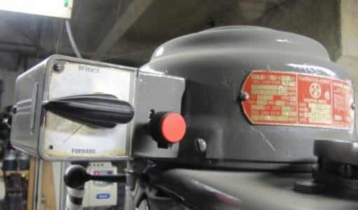
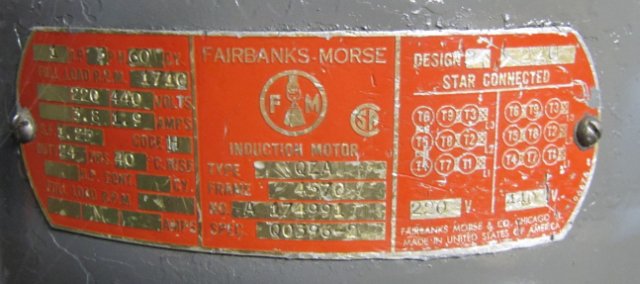
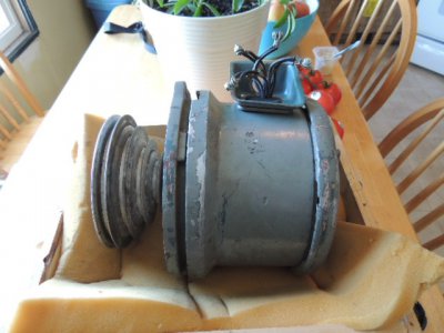
I have a 74 step pulley. I'm pretty sure it has original 1 hp motor. I can't find a data plate and need the info for getting a vfd up and going. Where can I find all that info? Does somebody have the same set up with a data plate still in tact? Is there a source for getting this info on the web?
-
Welcome back Guest! Did you know you can mentor other members here at H-M? If not, please check out our Relaunch of Hobby Machinist Mentoring Program!
You are using an out of date browser. It may not display this or other websites correctly.
You should upgrade or use an alternative browser.
You should upgrade or use an alternative browser.
motor data plate?
- Thread starter LEEQ
- Start date
- Joined
- Nov 26, 2010
- Messages
- 150
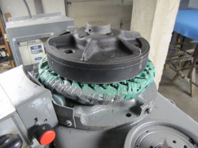
Your data plate appears to be on a cover and not on the motor itself. Is that right? If so that explains where mine is. Can you take a snapshot of the motor underneath? I thought that you could not use a drum switch with a VFD. How do you wire that up?
- Joined
- Nov 26, 2010
- Messages
- 150
Correct the plate is on the cover not the motor.
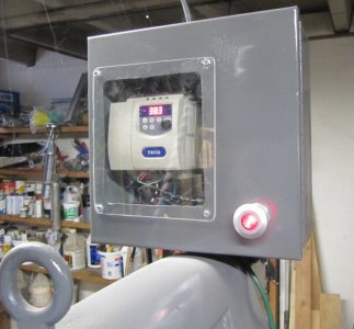
You are correct you cannot us the Drum switch with VFD with standard wiring. Switching the 3 Phase.
As I said I Wired the drum switch as a input! The drum switch is switching 24V to the VFD
On the Drive
#3 Common 24V.
#4 Input S1 Forward
#5 Input S2 Reverse
#9 10V. Pot
#10 AIN Pot
#11 Common Pot
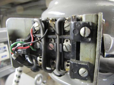
You are correct you cannot us the Drum switch with VFD with standard wiring. Switching the 3 Phase.
As I said I Wired the drum switch as a input! The drum switch is switching 24V to the VFD
On the Drive
#3 Common 24V.
#4 Input S1 Forward
#5 Input S2 Reverse
#9 10V. Pot
#10 AIN Pot
#11 Common Pot


- Joined
- Nov 26, 2010
- Messages
- 150
Do you have numbers on you wires?
Low voltage ...
L1---1--6--7
[FONT=inherit !important][FONT=inherit !important]L2[/FONT][/FONT]---2--4--8
L3---3--5--9
High voltage ...
L1---1 4--7
L2---2 5--8
L3---3 6--9
Three phase motor wire connections
First read the nameplate for wiring instructions. They are some times located in the “peckerhead” or junction box on the motor. If needed refer to the information below.
Determining wye or delta connection for motors
On delta connected motor lead #s (7,8, & 9), (1& 4), (5& 2), (3& 6) have continuity with each other
On wye connected motors (1,4& 9), (3,6 & 8), (7,2 & 5) have continuity with each other.
Wiring dual voltage wye connected motors
Low voltage L1=1&7, L2=2&8, L3=3&9, Join 4,5&6
High voltageL1=1, L2=2, L3=3 join 4&7, 5&8, 6&9
Wiring dual voltage delta connected motors
Low voltage L1=1,6,7 L2= 2,4&8 L3=3,5&9
High voltageL1=1, L2=2, L3=3 join 4&7, 5&8, 6&9
Delta connected motor, not wired, no lead markings;
Group each lead with the others to which it has continuity. Pay no attention to the very slight readings on the ohm meter as that is continuity thru the windings.Leads1, 2, and 3 should have one half the resistance to those leads to which they have continuity as the other two have to each other Arbitrarily name 1, 2, & 3.
Changing the voltage to a motor with unmarked leads now wired;Dual voltage Wye connected
Example motor is wired 440 volt connected.
1-Arbitrarily mark line, (to power), leads 1,2, and 3. And disconnect lines. Mark each individual wire of the three pairs of wires connected A, B, & C
2-Separate A&A and check each for continuity with 1, 2, & 3. 4 will have continuity with 1, 5 with 2, and 3 with 6. The one originally paired with 4 (A, B OR C), will be 7, originally paired with 5 (A. B. or C), will be 8 and originally paired with 6 (A, B or C), will be 9
Dual voltage Delta connected
Example motor is wired 440 volt connected.
1-Arbitrarily mark line, (to power), leads 1,2, and 3. And disconnect lines. Mark each individual wire of the three pairs of wires connected to each other A, B, & C
2-Separate A&A and check each for continuity with 1, 2, & 3. 1 will have continuity with 9 and 4, 2 will have continuity with 7&5, 3 will have continuity with 6 & 8.Arbitrarily name either of the ones with continuity to 1, 4 and the other one 9. The one originally paired (from pairs AA, BB, or CC), with 4 is 7. Name one that has continuity with 7 & 3, 8. Name the remaining one with continuity with 2, 5 and the last unmarked lead should be 6, which has continuity with 3 & 8.
Identifying Leads of a Nine Lead Three Phase Motor
Question: I have lost track of the leads of a nine lead three phase motor. How can I re-identify these leads?
Answer: For the purpose of this test, a lantern battery of six or nine volts works best. Use a DC volt-ohm meter with a 20K ohms per volt DC scale. Battery and voltmeter leads should be properly identified. Alligator [FONT=inherit !important][FONT=inherit !important]clips[/FONT][/FONT] should be used on both. The motor must be completely assembled. Test the nine leads for continuity with the ohmmeter to determine whether the motor is star (wye) or delta connected. The delta connected motor will possess three sets of three leads with continuity between them. On the other hand, the star connected motor will have only one set of three leads with continuity between them, and three sets of two leads with continuity. Following are specific steps to take when identifying leads of both a star connected and a delta connected motor. Refer to the diagrams on the following page for further details.
Delta Connected Motor:
Using an ohmmeter, identify the three groups of three leads. Separate these groups by tying them with tape. Attach leads to a pair of wires in a group, and observe the voltage drop from each pair of energized leads to the third lead in that group. Continue until a combination is found that gives a voltage drop from each of the energized leads to the third lead equal to one half of the battery voltage. The lead located halfway between the other two will thus be the corner lead of the delta. Repeat this for each group of leads, marking the corner leads #1, #2, and #3.
Next, use the inductive kick test method to identify the proper markings for the other two leads of each group. The two coils #3 & #6 and #3 & #8, acting in parallel, will produce the effect of a coil positioned halfway between the actual position of the two coils. The flux produced by #3 & #6 and #3 & #8 combined, will be perpendicular to the axis of #1 & #4 and #2 & #7. [FONT=inherit !important][FONT=inherit !important]Opening[/FONT][/FONT] and closing a switch in this circuit will produce a kick in coils #1 & #9 and #2 & #5, but no kick in #1 & #4 and #2 & #7.
Therefore, if the battery is connected from #3 & #6 and #3 & #8 as shown, opening and closing the battery circuit, the voltmeter will identify leads #1, #4, and #9 and can be distinguished by noting the magnitude rather than the polarity. The voltmeter can then be connected to terminal #2 for determination of the leads #5 & #7. Leads #2 to #7 will give little or no deflection, and leads #2 to #5 will give a substantial deflection.
In succession, the battery is then transferred to the corner of #1. Tie the battery between leads #1 & #4 & #9. Making and breaking the circuit will be perpendicular to #3 & #8 and #2 & #5, resulting in no deflection. However, there will be a deflection from leads #2 & #7 and #3 & #6. Placing the battery next on the #2 & #5 and #2 & #7 leads will be perpendicular to #1 & #9 and #3 & #6 leads, therefore creating no deflection. Leads #1 & #4 and #3 & #8 would then have a deflection, thus concluding the lead testing of the nine lead delta connected motor.
Star Connected Motor:
Mark the three leads with continuity, #7, #8, and #9. Clip the battery to the #8 & #9 pair, clipping onto one and flashing the other. Clip the voltmeter to each pair of leads with continuity between them, until a pair is found that produces little to no "kick" or deflection. This pair of leads consists of the #1 & #4 leads. Next, move the battery to the #7 & #8 combination, with the positive lead on the #7 lead and the negative lead to be used for flashing the #8 lead. The voltmeter is so placed on the #1 & #4 pair that an upscale deflection is observed on the "make" of the negative #8 lead. The voltmeter positive lead is then the #1 motor lead, and the negative voltmeter is the #4 motor lead.
Next, move the battery to #7 & #9 leads with the positive lead on the #9 motor lead, and the negative to flash the #7 lead. Identification of the #3 motor lead is then determined by an upscale kick. The positive voltmeter lead should be on this lead, and the negative lead should be on the #6 motor lead. Shift the battery to the #8 & #9 pair, with the positive battery lead on the #8 lead and the negative used for the flashing. An upscale kick will identify the #2 motor lead. The positive voltmeter lead will be found on the #2 lead, and the negative voltmeter lead will be the #5 lead. This concludes the lead testing of the nine lead star connected motor.
Last edited by a moderator:
"The basic wiring diagram is 1-7 to one phase, 2-8 to second phase, 3-9 to third phase and 4-5-6 hooked together to be the external star. be careful. Don't get shocked. " This quote represents the pairings. I will check continuity on these pairings tomorrow to be sure. I don't know for sure the volts, amps or hp though. Aren't these important? I don't know how to choose proper vfd without. If I had to guess it would be 220v 4amps 1hp. I can't just guess though. Any thoughts on how to find these things without a data plate?


