Motorized spinning grinding head

Technical Ted

H-M Supporter - Gold Member
H-M Supporter Gold Member
Joined
Nov 5, 2016
Messages
1,419
Head.jpg
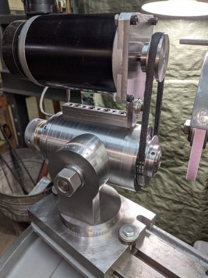
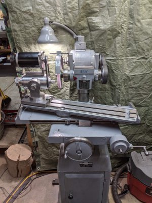
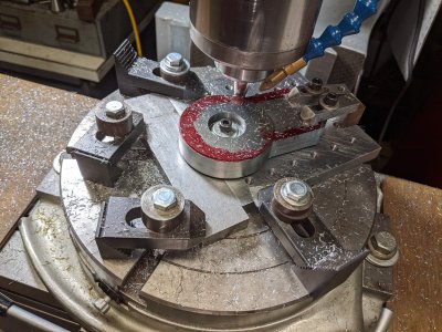
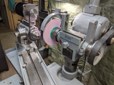
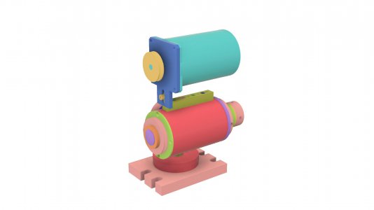
Just thought I'd share what I've been up to lately. I designed/built a spinning head for my grinders. One goal was to use materials I had on hand and that lead to some design limitations, but, after multiple design approaches, I came up with a solution.

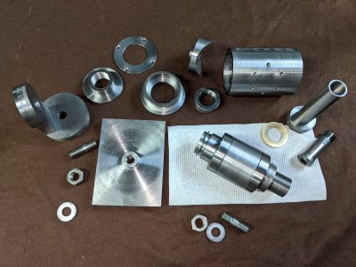
For the bearings I used a pair of replaced spindle bearings out of a Bridgeport head. These were given to me a while back and although used/replaced they felt and looked fine to me and since I'm only going to be running at probably 350 RPM max and light duty at that I figured they were worth a shot. They are working fine and sure beat spending hundreds of dollars for new ones!

I made the spindle from a piece of B7 bolt material I had on hand which is 4140/42 prehardened (similar to 4140 prehardened). I feel this material will work fine for my use.

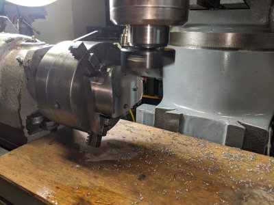
Collet wise, although I would have liked 5C, the bearings have too small of a bore for these so I went with my 4C collets. R8 would seem to make sense, but they have no through hole... I'm currently drawing up a 4C mount for a 3" four jaw chuck as well.

After assembly, the bore in the spindle runs within 0.0003" TIR. I'm very happy with this; it could have been a lot worse with all the machining/assembly variables involved. The right thing to do is to grind the spindle bore in on its' own bearings and I may do that, but I'm going to use it for a while and see how things go. My collets, although good brand names, are old/used and don't run perfectly true anyways. I test ground a piece of mild steel and could not detect any out of round condition at all.

The motor is a Parker Hannifin Compumotor stepper and drive. Way over kill for this application, but the only thing I had on hand that was around the right size, power and also has programmable speed control. This made pulley sizing completely irrelevant.

I didn't want to add any additional stresses so instead of welding I used screws and dowel pins for assembly. The only components I had to purchase were oil seals (not to keep oil in since I greased the open bearings, but to keep grinding dust out), the belt (2L V belt) and some fine thread hex head cap screws.

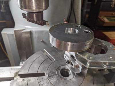
With the threaded top rail and locking flange nut assembly on the rear I left things open to add an 24 position indexing plate and lock pin for indexing, which I'll be designing soon.

Works great!
Ted
Motorized Work Head.jpgGrinder with head.jpgDegree lines.jpgFlybar side swivel.jpgMill side.jpgParts.jpgMotorized grinding spin head a.jpg
 
Very nice job, Ted! If the v-belt causes vibration and/or runout in use, try using an appropriately sized o-ring instead. They run much smoother, and you can always switch back to the v-belt if you are doing a job that requires more torque (most jobs do not.) The o-ring can run in the same pulleys you are using now. O-rings are somewhat safer, too, than v-belts when exposed...
 
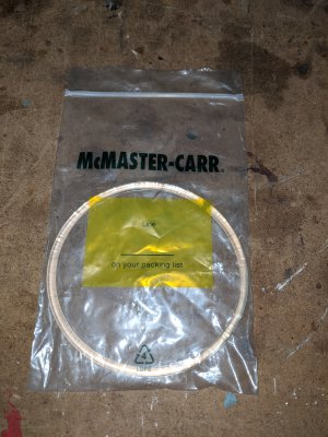
Thanks Bob. I was originally thinking the same thing. I ordered a 1/4" round Polyurethane Rubber belt from McMaster Carr. This material is suppose to be more resistant than the black O-ring type belts. The problem was the two oil seals. They fit so tight they added way too much resistance to rotation. I even machined some off the mating surfaces to get the fit I liked, but the belt still slipped some... enough to heat up the pulleys which in turn headed up the spindle. So, I switched to the 2L belt and it worked out beautifully! No vibration, slip or problems whatsoever!

I love McMaster, but sometimes the shipping costs more than the product , which was the case when I had to order the 2L belt. The round belt will go into my parts department! ;)

Thanks,
Ted

IMG_20200520_104552.jpg
 
Typically, precision spindles do not use seals, only laberynth or felt closures that do not drag. My B&S Micromaster uses a multiple O ring drive for the spindle, it is smooth and capable.
 
I used a j3 serpentine belt on mine. They have less drag and more traction than a V belt or an O ring.
 
I had a Leblond cutter grinder years ago, early 1900s, I made a setup to cylindrical grind between centers, made two cone pulleys of steel with 3 steps, radiused in the root diameter and used a leather sewing machine belt to drive it, laced with copper wire. This was in the mid 1970s.
 
Typically, precision spindles do not use seals, only laberynth or felt closures that do not drag. My B&S Micromaster uses a multiple O ring drive for the spindle, it is smooth and capable.

I agree. I originally looked into making something like they use on Bridgeport mills, but felt for a spindle in the horizontal position (vs vertical) and with the fine grinding dust that it would not be adequate. I found some spindle design information on-line from a bearing manufacturer that stated installing oil seals backwards was best when used solely for keeping dirt out, so that is what I did. Now that I have the fit I want on the sealing surfaces and a good belt (2L V belt) it works great! Very smooth, very nice finish and I can't see any out of round condition on my grind. The oil seals should do a great job at keeping the dust out of the bearings and they were an easy/inexpensive thing to use.

Thanks for the suggestions,
Ted
 
If it performs as good as it looks then you have a winner.
Very nice build.
Chucl
 
Back
Top