- Joined
- Feb 7, 2013
- Messages
- 15
After reading Bill Burton’s excellent article on installing a 140 Servo drive on his Clausing, it gave me the needed incentive to get started on a similar project. I’ve had a used 140 Servo for several years & since it wasn’t a complete kit, I took a different approach . As Mr. Burton correctly pointed out, the Clausing was the first mill the Servo was designed for. Unfortunately bevel gears with a 7/16” bore are no longer available which complicates the project and requires us to modify the available gear designed for the Bridgeport, but all is not lost. By using the existing Clausing spacer sleeve on which the dial rotates as a keyed driver (more on the later) and fitting the gear to it, we now have solved the problem while retaining full functionality (and reversibility) should we want to revert back to manual drive in the future.
As I replaced the right end bearing carrier with the Servo, the 2 dowel pins are not required and in fact interfere into the space where the bevel gear needs to reside. Also, Servo didn’t furnish holes in the housing for them in the correct position. The pins can be removed or shortened (my choice) which allows for a direct bolt up after slotting holes for them in the Servo housing for clearance. The Servo uses a needle bearing for the Bridgeport installation(discard) which is a different OD than the bearing on the end of the Clausing leadscrew. A very thin wall section sleeve of approx. 1.3155”(ref) od x 1.262”(ref) id x 1” long bushing solves this issue. Once this part of the project is complete and the Servo attached, the mill will operate in manual mode just as before but without the bevel gear installed.
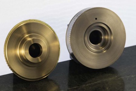
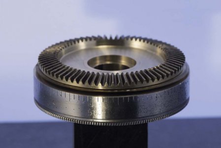
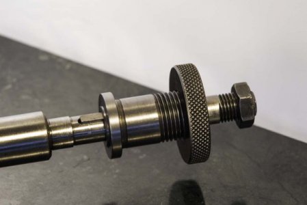
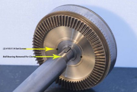
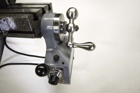
As the attached photos will reveal, I took time to clean up the bevel gear casting by machining material from both faces. This was done partly to gain clearance for the flanged head of the original Clausing dial spacer and also to not remove any more material than necessary from the backside of the dial. I made an expanding arbor to hold the gear from the flat side when machining. By looking at the photos you will be able to see what I mean. I added a keyway slot in the bore of the dial spacer and a keyway groove in the leadscrew shaft which will now drive the gear. The gear is Loctited to the spacer and 2 setscrews act as pins to give the drive a solid connection (see photo for location). To get the correct gear mesh, some spacing with shims will probably be required. Shims of the correct size are available from Mcmaster-Carr. Needless to say concentricity should be maintained in all machining processes. I didn’t include dimensions as they are not critical if you keep the overall concept in mind. My mill is s/n 555 which is very early, so I suspect some changes may have taken places in succeeding years.


