
I don't really understand your explanation, it is very complicated. here is a picture of the chart of my chinese lathe, i tried 10 different thread combinations and none i got the right resultLet me try to help. You haven't posted any pictures of your lathe, and I know nothing else about it. Apologies if this is already known to you. But I'm going to get pretty basic and somewhat generic, just for the sake of completeness.
1. I assume you have gears both in the headstock and in a QCGB (quick change gear box) just ahead of the leadscrew. The thread pitch will be a combination of both gear sets, plus the lead of the leadscrew.
2. Headstock gears - If a series of gears is meshing with each other (ie, in a common plane), then intermediate gears don't affect the final ratio. The ratio is determined by the tooth counts of the first and last gears only. If a pair of gears is on a common shaft (ie, cluster), with previous gears driving one of them and subsequent gears being driven by the other, this tooth ratio must be multiplied in.
3. Commonly used sets of cluster gears for metric threads are shown in the table below. Only the 127/120 gives "exact" metric threads on an inch lathe, or "exact" inch threads on a metric lathe. The last column gives the thread pitch error of the alternate sets. You mentioned having a 56 tooth gear. It should be "clustered" with a 44 tooth. Assuming you have an inch lathe - your leadscrew has threads evenly divisible by inches, you'll want the headstock gear (and intermediate gear if used) to drive the 56 tooth gear. Subsequent gears should be driven by the 44 tooth gear.
View attachment 341687
4. If you have a QCGB, you'll want to open it up and do tooth counts of all the gears. This will give you a set of possible ratios. Note that the last gear in the headstock is on a shaft common with the gear(s) in the QCGB, so this constitutes a cluster. If no QCGB, you're driving the leadscrew directly from the last headstock gear, so no additional ratio needs to be factored in.
5. Once you've calculated the turns ratio between the spindle and the leadscrew, you multiply by the pitch (inches per turn) of the leadscrew to get the inches of carriage movement per spindle turn ... the thread pitch you will cut.
Here are two gear calculators that might be of help:

Change Gears for Threading
This calculator determines the correct change gears for any thread pitch. Works for all mini lathes and HiTorque Bench Lathes.littlemachineshop.com
And here's the diagram I made for metric threading on my 12x24 lathe. Note the pictorial in the upper left, showing how the gears are arranged. The "A" gear is on a shaft driven by the spindle through some internal gearing, so it's part of a cluster, and thus becomes part of the final ratio. The "SET" column indicates the settings of the two levers of my QCGB.
View attachment 341688
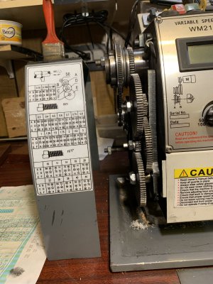
If you could, please go ahead and post some photos of your headstock gearing setup, etc. Given specific info, I (we) can offer more specific advice.

-
Welcome back Guest! Did you know you can mentor other members here at H-M? If not, please check out our Relaunch of Hobby Machinist Mentoring Program!
You are using an out of date browser. It may not display this or other websites correctly.
You should upgrade or use an alternative browser.
You should upgrade or use an alternative browser.
MX210 D/S MT5 8x16 lathe review
- Thread starter greenail
- Start date
- Joined
- Feb 17, 2013
- Messages
- 4,406
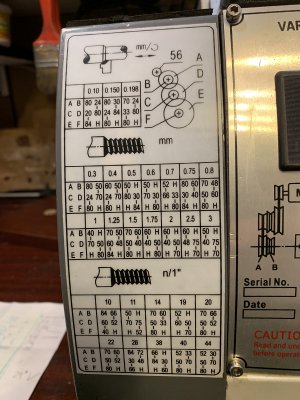
That's a strange looking chart! I can only guess what the "H" means - probably something like "immaterial," because whatever other gear there is mounted on the common shaft is not used. I'll also assume that the vertical dashes on the chart indicate meshed gears.
Let's check something first ... is the gear on the spindle 56 teeth? If so, you can probably use the following setup. If not, I don't know what to tell you.
As best I can interpret the chart, for 0.5mm thread, you mount a 50 tooth gear and "anything else" on the upper post. Per the vertical hash mark on the chart, mesh the 50 tooth "A" gear with the 56 tooth spindle gear above. Place 80 tooth and 30 tooth gears on the second shaft. Mesh the 80 tooth "C" with the 50 tooth "A" gear above. The bottom shaft (which I guess drives the leadscrew directly) should have an 84 tooth and "anything else" on it. Mesh the 84 tooth "F" gear with the 30 tooth "D" gear above.
This combination should give you a ratio of 56/80 X 30/84, or 0.250 leadscrew turns per spindle turn. If your leadscrew has a (metric) pitch of 2mm per turn, you should get a metric thread of 0.5mm. (56 teeth per spindle turn) X (30 teeth/80 teeth) X (1 leadscrewturn/84 teeth) X (2mm/leadscrew turn) = 0.5mm per spindle turn.
That's the best I can offer. If this does indeed get you 0.5mm threads, you now hve a "template" to follow for other threads. Again, if I've misunderstood the symbols on the threading chart, I don't know what else to say. Good luck!
I added an electronic leadscrew (half implemented) and you can see some of the surface finish it was able to produce in some mystery metal and aluminum. I re-machined a 6" backplate and saw a really good surface finish for the first time around 2" from the center. The backplate was bolted directly to the spindle flange so it was as rigid as you can get with this lathe. It was quite a joy to see the nice blue chips and such an amazing surface finish. I don't think i'm brave enough to run the thing at a high enough RPM for the smaller diameters and carbide to make a really good finish. The spindle wall is just so thin I wonder what would happen if it was running 2k rpm and it failed!
An additional complaint. While the thing is actually running pretty well with the tweaks to the bearing preload, removal of the cross slide, and lots of attention to shimming the saddle, it has very severe increase in thickness of the bottom surface under the front way. This makes it crazy tight and almost unmovable when the tool is moved up close to the spindle flange. This may have added the rigidity needed to product the great surface finish I got on the backplate but it is too tight to be practical. With the chuck on this isn't so bad and I haven't bothered to try to scrape it in.
I bought new timkin bearings for it but I have not put them on yet. I'll let folks know if that is an improvemnt when I get around to installing them.
The lathe will cut metric threads no problem with correct gears.
Imperial threads as well except you cannot disengage the lead-screw you need to backout and run in reverse back to starting point to start your next pass.
When cutting 1mm threads (25.4TPI) you can engage and disengage the lead screw whenever you want.
A C E are the left side gears, BDF are the right side gears.
The spindle gear 56 tooth is not shown in the chart but is needed in the calculation. So to calculate you start on the left side top 56spindle not shown divided by last gear on that side(any gear in the middle is just an idler only fills the gap). Times the first gear on the right side divided by the last gear on the right side. This is the ratio of chuck revolution to lead screw revolution.
Lead screw is 2mm so you multiply the ratio with the 2mm lead screw and the amount of travel you get per chuck revolution. If you travel 1mm per chuck revolution well you are cutting 1mm threads. If you travel 1.5mm per REV you are cutting 1.5mm threads. IF you travel .9071mm per REV you are cutting 28.00 TPI . Pretty simple.
Now for the calculations for the gears needed to cut threads not very simple, a gear calculator is really needed. But with the basic math above you can check if the gears will work. To cut imperial with a metric lead screw you are best served with a 127tooth gear but other gear sets can get you very close. Best program I have found is change gears.js you add your lathe dimensions and gears you have and it will calculate the setup.
Add a lathe MV-210 wheel on headstock 56 tooth, Pitch of lead-screw 2.000 mm, smallest size fo 1st wheel 50, Min difference 10, modul 1.0, 150mm , 140mm. Now enter your gears you have and click ok.
Now you can calculate what gear combo's will cut what threads. 3D printed gears work fine I have not broken a single tooth yet.
A 127 tooth gear will add accuracy to gears needed to cut Imperial threads as well as very fine cutting .002 cut per rev (approx 461 TPI) . Printing combo gears makes changing gears faster as you only need to slide them on the shaft no keyed insert needed as the gears are printed together.
Here is an example going from metric 1mm pitch to 24TPI only need to change middle set and adjust middle and top gear shafts for proper distance. Use a folded piece of paper to space gears so they turn freely. Slide folded paper strip in between gears and press gears together while you tighten the shaft they are mounted on. This will give them a little space to turn freely, makes a big difference.
1mm
top post 84 xx mid post 28 20 spindle shaft xx 80. .....56/28 (84 idler doesn't matter only 1st and last gear in the same row matter) x 20/80=.5 ratio chuck to lead screw x lead screw pitch 2mm = 1mm travel per chuck rev. .....84 gear is a fill the gap gear (idler) does not count you can substitute it with a smaller gear if needed. xx is a spacer.
24TPI
top 84 xx mid 41 31 spindle shaft xx 80 . .....56/41 x 31/80 =.52926829 ratio x 2mm lead screw = 1.05853659 lead screw travel per 1 chuck rev in mm ......now to convert this to inches 25.4 / 1.05853659 travel per rev in mm = 23.995 TPI
Hope you can follow.
Graphic display of gears in the change gear program will be mirror image so left gears go on right side and vice versa.
You can see this as only one side attaches to the spindle gear.
Attachments
Last edited:
I just bought one of these that didn’t come with a chuck at all.
Anyone have an extra that they have replaced with a better one?
Any suggestions on a quality aftermarket chuck that has a sufficient through bore but doesn’t break the bank?
-Jim
Anyone have an extra that they have replaced with a better one?
Any suggestions on a quality aftermarket chuck that has a sufficient through bore but doesn’t break the bank?
-Jim
The k12-160 is cheap 4 jaw but you will have to make an adapter plate or cut the register on the lathe spindle to 65mm and drill and tap 4 bolt holes. Front mounted bolts thru chuck so not a big deal. 6” 4 jaw with 1.625 pass thru. About $86 eBay shipped.I just bought one of these that didn’t come with a chuck at all.
Anyone have an extra that they have replaced with a better one?
Any suggestions on a quality aftermarket chuck that has a sufficient through bore but doesn’t break the bank?
-Jim
It's really nothing of importance but having read on various forums people wondering about what H means, here's my take, it doesn't stand for a word in any language, it just graphically reminds of the spacer - two vertical faces with a through hole.That's a strange looking chart! I can only guess what the "H" means - probably something like "immaterial," because whatever other gear there is mounted on the common shaft is not used.
Also wanted to share this gear calculator which covered perfectly a 40T spindle while no other did
http://kachurovskiy.com/gears/
Last edited:
- Joined
- Feb 17, 2013
- Messages
- 4,406
Durn! I think you've nailed it. Never even thught of that possibility. Many thanks!It's really nothing but having read on various forums people wondering about what H means, here's my take, it doesn't stand for a word in any language, it just graphically reminds of a the spacer - two vertical faces with a through hole.
Adding a 127 gear makes cutting Imperial possible with .001 accuracy.It's really nothing of importance but having read on various forums people wondering about what H means, here's my take, it doesn't stand for a word in any language, it just graphically reminds of the spacer - two vertical faces with a through hole.
Also wanted to share this gear calculator which covered perfectly a 40T spindle while no other did
http://kachurovskiy.com/gears/
You can change the spindle gear to whatever your lathe uses.
38mm big bore versions use 56 tooth spindle.
You can change the spindle gear to whatever your lathe uses.
I did a comparison of the two applications mentioned, but ran into a problem with ChangeWheels.
I entered my lathe data to the best I could understand some parameters
For 1mm pitch It gives the following:
Evidently, of all the possible alternatives, the program only gives the one with the biggest available gear as first, but that won't work well with my lathe, as the quadrant cover wouldn't fit, one would have to work without it and the safety switch pushed. I really recommend against that.
Of course If I remove from config all gears above 60T I get an usable setup, but that is not a good solution as will not work with all pitches.
So, to be really applicable to any lathe the program would need to list all the alternatives, and/or support additional gear size parameters.
On the other hand, Kachurovskiy's online calculator is simpler, does not consider any physical constraint, and shows all the possible alternatives for a given pitch and the nearest approximate ones
as well all the possibly supported pitches, and a simple graphical representation. I like it for two more reasons, first being browser based it can be used on a mobile device when one is to the lathe, and then since it's open source it has room for any kind of improvement.
Anyway, the original reason I went looking into calculators is that I will need to cut a non-standard pitch for an antique clock restoration.
Calipers was at 6mm in the pic above, and my assumption is that is a 1/4 of French Ligne, or 0.56mm.
I haven't defined yet the pitch diameter or profile. Both applications give a consistent solution for this pitch, and with that I hope to be able to cut my very 1st thread successfully.
Last edited: