[How do I?] My 2017 Rotary Phase Converter Build

I believe they just use a 240V to 110V step down transformer and the Neutral remains in the circuit. L1 (110V) N & E
Possibly, I read about it quite some time ago.
 
I fond this article It has some designs using the neutral, I think the one using the "dual primary transformer" might work for you. That way you could also boost up to 415V before the idler instead of using the idler as the boost transformer, as the guy in the Youtube video is apparently doing.
 
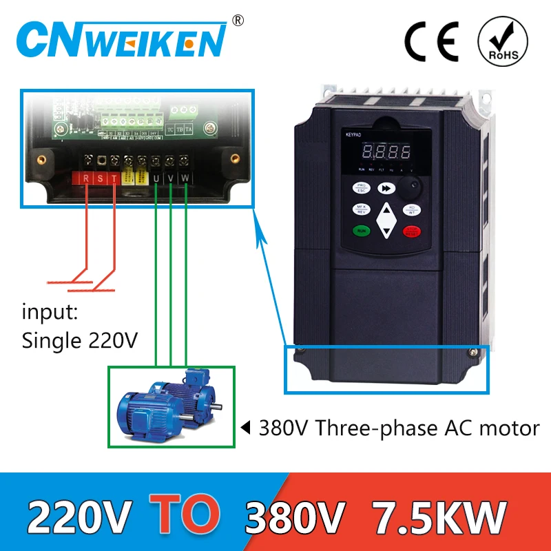
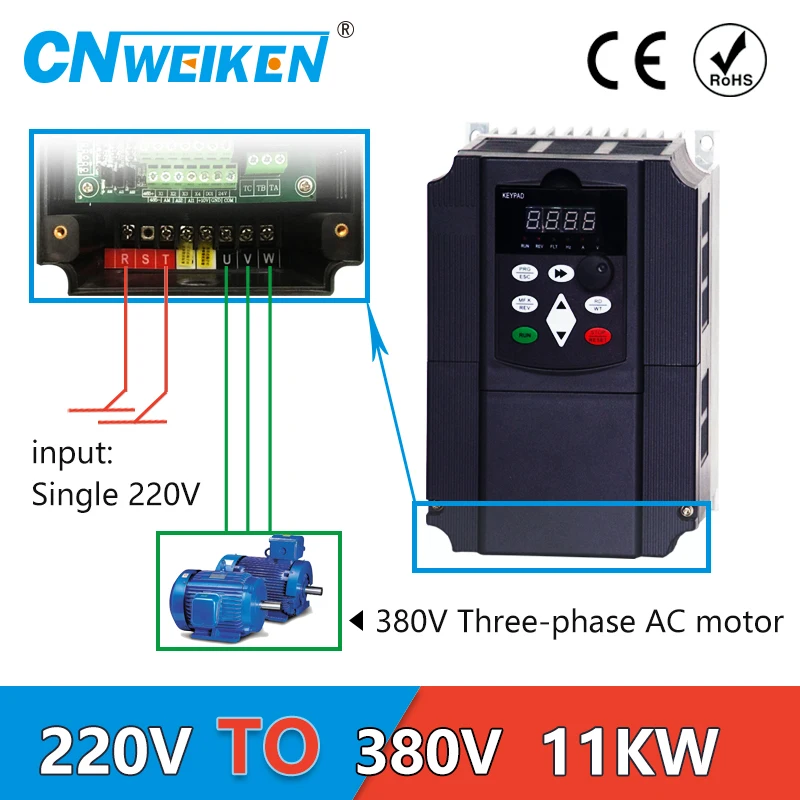
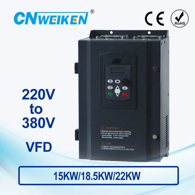
I really don't want to use multiple VFD's, because they would all need to be wired back to the consumer board taking up more space and AMP's than just one large RPC,

VFD's are designed to be mounted on the machine with a short a run of cable between motor and vfd as possible. Nothing different providing power to a vfd than supplying a large single phase motor on a machine. As far as space and amperage: VFD's are small, and how many machines can you run at once? Idle current on a vfd is milliamps and startup current is limited with the soft start. I have a 40A 230V supply to my garage with a small consumer unit in the garage. A few three phase machines, each with their own VFD. The larger ones are on 16A commando sockets, the smaller ones just on a standard 13A. I've never had it trip once; it just works. I did look at an RPC solution as my mill motor is awkward, but it worked out way more expense and faff to put an RPC in than rewire the motor and buy a few drives, plus I get all the bonus features of VFD on all my machines. I know you're keen on an RPC, but I'd definitely question whether it's the best solution here.

My 2p worth, having looked at the RPC route myself and gone the other way.
 
I fond this article It has some designs using the neutral, I think the one using the "dual primary transformer" might work for you. That way you could also boost up to 415V before the idler instead of using the idler as the boost transformer, as the guy in the Youtube video is apparently doing.

Thanks for looking and providing this information, I can't follow the path of the Neutral in the Dual Primary design, so I had a go at drawing one using a Neutral and Step-Up Transformers. I have know idea if you are allowed to Step-Up twice within a circuit, but the Dual Primary design you showed must be using a second Transformer (albeit a Step-Down type), the first being by the electric supply company before the power is brought to the consumer board (like how you have already mentioned happens in the USA).
 

Attachments

  • RPC Electric Circuit Diagram using Step up Transformers.pdf
    55.6 KB · Views: 6
Thanks for looking and providing this information, I can't follow the path of the Neutral in the Dual Primary design, so I had a go at drawing one using a Neutral and Step-Up Transformers. I have know idea if you are allowed to Step-Up twice within a circuit, but the Dual Primary design you showed must be using a second Transformer (albeit a Step-Down type), the first being by the electric supply company before the power is brought to the consumer board (like how you have already mentioned happens in the USA).
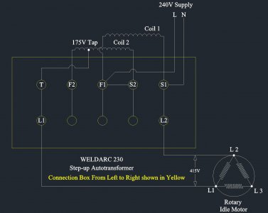
I don't think you need two transformers, one that will step up the incoming 240V to 415 is all you need, then the rest is just as the standard RCP design. No three phase motor needs a neutral. I suppose you could try messing around with it but I don't see the point. The only mention I can find of anyone making an issue of needing a neutral to a three phase motor it is that guy on the YouTube video. If you need a 240V to neutral to run ancillary circuits, simply run a separate line for them, no need to run it through the motor. Not sure why you want to reinvent the wheel.
 
Also take a hard look at VFD's they may be your best solution. FYI, I run all common methods of phase conversion in my shop, Static, RPC and VFD. They all work well.
 
Per what Eddyde indicated above. The other thing to consider is motors are rated for +/-10% voltage input, so a 415V motor would run fine on a 380V VFD. The are numerous 220V single phase input to 380VAC output on Alliexpress, and I am sure shipping would be a lot less to Australia. I do not use any of their VFDs in my systems in the US because of poor reliability and warranty issues, but would seem an easy/simple solution for your purposes. On a 7.5Hp compressor load I probably would go with a 11kW version. If this was run in a straight V/Hz setting you could power other 3 phase motors, but you would not have the overload protection, as this would be set to the maximum size motor. These are cheap enough that you could use one VFD per machine. You are still you are limited by your 220VAC single phase source which is 8.8kW. Also a 40A circuit is not designed/spec. to give a full 40A continuously and it will over heat your wires. The assumption is that the continuous rating is something like 80%, of the circuit rating at least in the US. Push all these factors = fire.
7.5KW 10HP 400HZ VFD Inverter Frequency converter single phase 220v input 3phase 380v output 18A for 7.5HP motor
11KW 15hp boost Frequency inverter single phase 220V converter to three phase 380v AC power transformer for motor VFD 650HZ
WK310 220V input to 380V output inverter 15KW 18.5 kW 22kw motor frequency converter controller Hoist converter
 
Thanks for the last lot of responses, like I have already mentioned I don't want to go down the VFD route because some of my machines have more than one 3 phase motor and some also have a 240V requirement.

I spoke to someone here in Australia who has built a number of RPC over the years and I have followed his suggestion and bought an old Arc Welder for $50

It is the type that allows 240V, 415V and 480V inputs (these are all single or 2 phase input voltages NOT 3 phase) on the Primary Winding, which allows for it to be used as a Step-up Autotransformer because the Primary Winding is Tapped.

I have attached a pic of how I have wired it up and it works great, giving me 415V to connect to L1 & L2 of the Idle Motor.

A nice cheep way of getting 415V from 240V single phase supply
 

Attachments

  • Welder used for Step-up Autotransformer LEFT to RIGHT.JPG
    Welder used for Step-up Autotransformer LEFT to RIGHT.JPG
    139 KB · Views: 13
Glad to see you've worked it all out, and didn't break the bank doing it. Much better and safer arrangement than the YouTube gizmo, IMHO.
 
Back
Top