- Joined
- Dec 13, 2016
- Messages
- 142
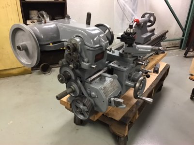
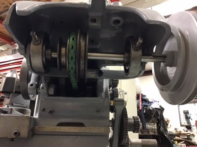
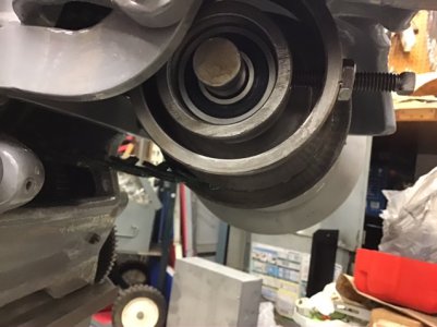
Another update... Installed the countershaft/cover using ball bearings instead of bushings so lathe assemble is finished. Will need to level/adjust/align the lathe when it gets mounted back on the cabinet.
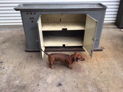
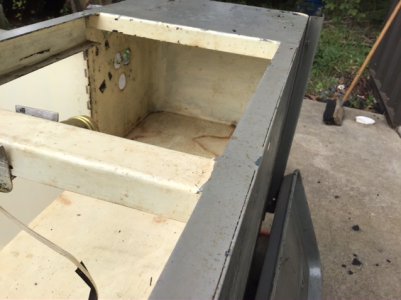
Started work on the cabinet. Plugging unused holes, weld some more steel in to stiffen it. Will then paint it.
Plan to replace two light bulbs with LED and use a push button light switch to turn on when door is opened.
How many people actual bolt down/anchor their light lathe to the floor?
The lathe is currently bolted to two wood runners. Thinking setting cabinet on rubber stall mats.
Bob G.
Attachments
-
 F47AB5D2-0A8D-4E55-BB8E-0D2FCA7A74E6.jpeg112.6 KB · Views: 31
 -
 8D5915FE-99BA-4DEE-8FD9-338E26C56A51.jpeg91.4 KB · Views: 32
 -
 EE7FA38D-99DD-4EFF-A3A8-D2E3F245A9BD.jpeg94.8 KB · Views: 38
 -
 125D10A0-5240-4F10-BCD8-ED3211FEE594.jpeg87.2 KB · Views: 37
 -
 87543BF0-804C-45DA-BC19-843565C5D827.jpeg83.4 KB · Views: 32
Last edited: