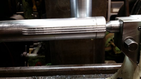
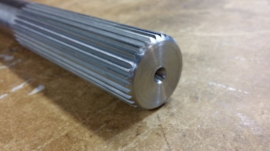
My first (and second) attempt at cutting splines.........

Okay, I had a problem with the first spline.....good thing it was just my test piece.......

Measuring for proper depth of cut of a spline is done by holding specific size gauge pins in two opposite grooves and measuring over them; like measuring threads with wires.

My measurements showed is was a little big, and tapered.....more than I had hoped. My target was 1.465"
When I checked my aluminum test part I measured 1.466" at one end and about 1.476 on the other (over the two 0.080" gauge pins).
The splined section is only ~3 inches long.

The bad news is that the small end was towards the "handle end" so it could not even be tested in the motor female spline.
No problem, just whack it off and re-chamfer.
I even stamped the measurements on either end and it became our "spline gauge".
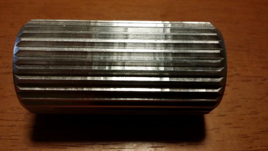
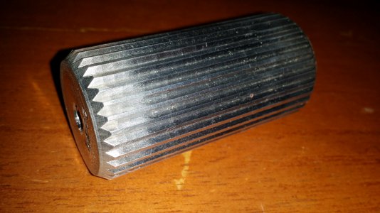
spline1_parted1.jpg

spline1_parted2.jpg

My friend found that it did mate....for about an inch, and then got tight.

This piece was not long enough, or strong enough to be used for the end purpose.
But as a test vehicle, I considered that a success!

-brino


spline1_parted1.jpgspline1_parted2.jpg
 
So you need a better way of tramming your rotary table in and you're probably good to go. I'll look forward to the next installment :)
 
AWESOME!!!
I swear, you guys are LIGHT YEARS ahead of me for sure.
And to think my cutting a keyway yesterday was a big deal!!
At least my hat fits better now :grin:
 
Okay, where did those errors slip in?

1) I measured it coming off the lathe and already had some taper there.
2) I made a mistake in mounting to the mill....but I figured it out and have learned from it......

Here's the mistake:
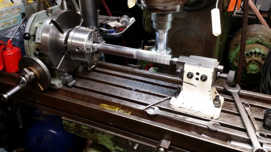
When I first moved the part from the lathe to the mill, I still needed to bolt-down the rotary table and the tail-stock support.
I finger tightened the rotary table clamps, and lined up the tailstock loosely.
I put an indicator in the spindle and ran it across the front of the part, slowly fixing the angle and tightening down.
I still believe I had the front edge straight with the table and x-axis.
....but then, I cut the grooves on the backside of the part!

Because of that existing taper, the backside of the part was NOT aligned with the table x-axis.
That would make the splines tapered too; cut deeper at one end than the other!

I can do better!

-brino
 
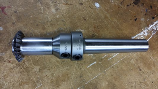
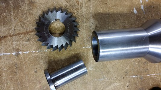
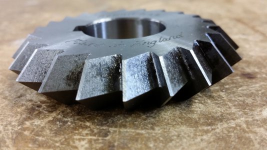
Okay here's some info/shots of the cutting tool I used.
I do NOT know where I got it....It might have come with the mill tooling, or it might have been from the local new/used tool store.

The cutter is a 90 degrees included angle and is about 2-3/4" diameter. It is HSS with a 1" hole.

I mounted it on an arbour and mounted that into a 1" end-mill holder that matches my mills' #11 B&S taper.

tool1.jpg

1585008217185.jpeg

tool3.jpg

still more to come........

-brino


tool1.jpg1585008217185.jpegtool3.jpg
 
Alright! Before starting the real long, steel spline I needed to upgrade a couple things......

1) Since this part is going to be about 12" long (~4.5" of spline at each end) I needed a lathe steady rest to hold it while I added centre holes.
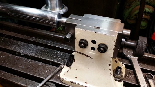
2) I needed a better tail-stock to match my rotary table.

Sure I could build them, but I want to do these other projects more......
For the steady rest I found a used on on ebay, that looked about right. It fit the bed fine, but turned out to be from a 10" lathe so the centre height was a little off. I solved that with some "offset fingers".

I found this tailstock at my local used tool store. It needed a little work:
  • the centre was cut/drilled and needed to be cleaned up, and
  • I had to take about 50thou off the casting to allow the adjustable centre to go just a smidge lower.....
spline2_better_tailstock.jpg

For raw stock, I found some 1.375" steel shaft, that had the perfect starting OD.

The first few grooves go very slow. I wanted to cut in two passes to full depth.
Obviously, to get a measurement I need to cut one groove and then crank the handle 45 turns and cut another.
Only then can you measure it while juggling the two gauge pins and the micrometer.....
I did a few of those to help dial in the depth of cuts.
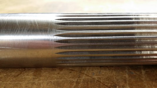
I found a combination that seemed to measure perfectly (first pass depth 25 thou, second pass depth 38 thou.)

spline2_first_cuts.jpg

spline2_cutting.jpg


View attachment spline2_front.mp4


View attachment spline2_back.mp4


I have one more video I'll try in the next update......

-brino


spline2_better_tailstock.jpgspline2_first_cuts.jpgspline2_cutting.jpg
 
Learning a lot, I guess the key way is not needed, I have an arbor without also.
 
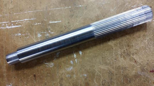
Here's a few shots of the long (~4.5 inch) steel spline on the 12" shaft....one end done, now (after test fit) I just gotta do it all again!

The reduced end is for mounting an rpm indicator for bench testing.
spline2_full_shaft.jpg

spline2_closeup1.jpg

spline2_closeup2.jpg

Still trying to cut down one more video...it may not be available tonight.

-brino


spline2_full_shaft.jpgspline2_closeup1.jpgspline2_closeup2.jpg
 
Back
Top