My First Clock - The Silver Lady

Dataporter

Active User
H-M Supporter Gold Member
Joined
Jan 20, 2013
Messages
270
We used to have a joke at my office about one of my talkative co-workers. The joke was, ask him what time it is and he would tell you how to build a clock! Well, I'm not going to tell you how to build a clock because Brian has written a book! Also, I don't know how to build a clock, yet... So what I am going to do here is just share my build of Brian's Dark Lady Clock. I'm hoping that if I get stumped or have a question, Brian or someone else here can share some advice. Brian did a thread right here on his build of this clock. Brian's plans are for building the clock with minimal tools and on the cheap material wise. I'm calling mine the Silver Lady because instead of blued steel for the frame of the clock I'm using some stainless steel that I have. The stainless brushed with a brass wheel looks silver and Silver Lady seems like a more romantic name than Stainless Lady. I'm also going to use more brass etc because I can. I'm using my 3 in 1 instead of a 7x10 mini lathe and I have rotary table / dividing head and some other tools. I elected to buy a mod 1 gear cutter. The plans are in metric and this is my first experience with metric. Most of my digital tools and my DRO switch from inch to metric with the touch of a button. My brain does not. I got a nice conversion chart and a metric ruler and a Harbor Freight 0-1" 0-25mm digital micrometer (which seems to be very usable). Of course, the good old USA missed the metric boat, unfortunately, and I have to use material that is the closest fraction of a inch in many places. I hope I don't screw that up!

Here's a picture from Brian's Website of what his clock looks like...
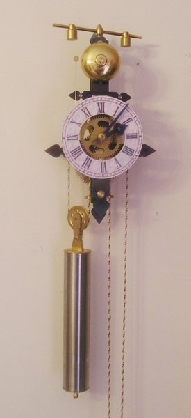
4632317.jpg
 
Last edited:
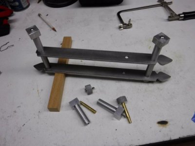
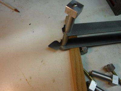
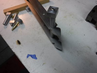
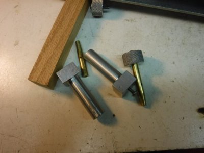
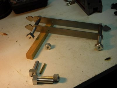
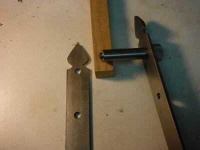
Here is some pictures of the frame (so far) and the assembly tools that I have made. I've actually improved the assembly tools a little. You'll see the improvements in later posts.

DSCF0015 (Medium).JPG DSCF0016 (Medium).JPG DSCF0017 (Medium).JPG DSCF0018 (Medium).JPG DSCF0019 (Medium).JPG DSCF0020 (Medium).JPG
 
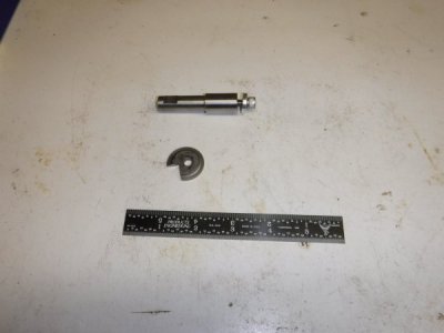
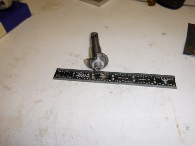
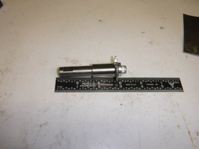
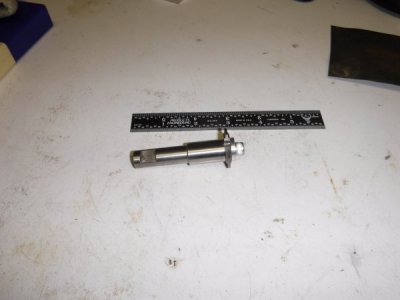
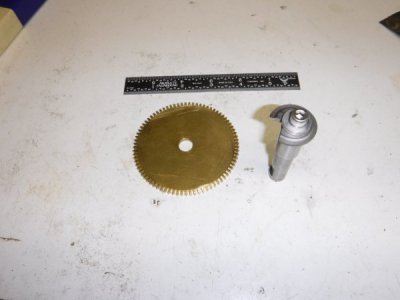
The escapement arbor is shown in one of the last photos in the thread above. The arbor has to be concentric so both sides were turned and faced and the hole was drilled through the center without removing the stock from the chuck.
DSCF0060 (Medium).JPG DSCF0061 (Medium).JPG DSCF0062 (Medium).JPG
 
Here is the MOD 1 Cutter that I bought to cut the wheels (that's how a clock maker says gears, I guess). I made the arbor. Brian's Dark Lady plans have easy plans and instructions for making the cutter. I thought about making my own, I'm sure I could have, but in the end, I bought this one...

DSCF0143 (Large).JPG DSCF0137 (Large).JPG DSCF0136 (Large).JPG DSCF0135 (Large).JPG

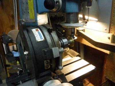
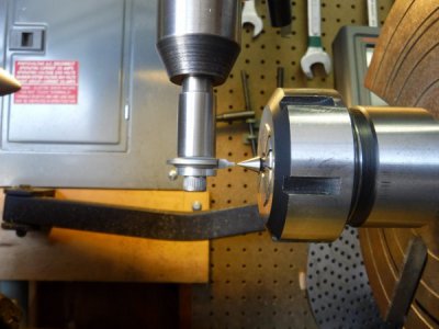
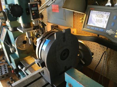
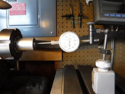
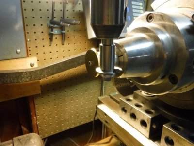
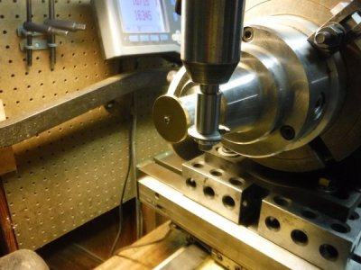
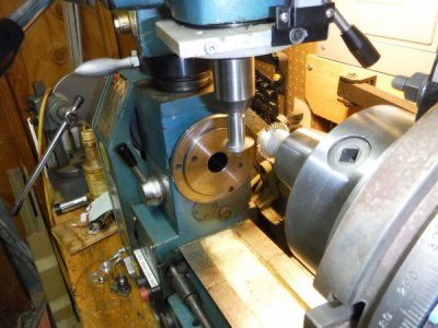
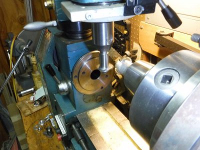
Below is how I lined up the cutter to be on center. As a side bar, I was using this ER-40 chuck mounted in the Morse Taper 3 hole in the center of my rotary table. Before I cut the first gear, I decided to check the run out and it was nearly .010"! (0.25mm) I decided that was unacceptable and you will see later that I mounted my 5C chuck on the RT instead.

DSCF0085 (Large).JPG

My understanding is that the cutter can be sharpened many times by simply grinding the leading face of the cutter.
 
Last edited:
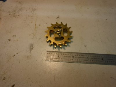
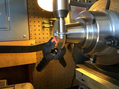
Cutting the Main Wheel. This is the first wheel or gear I ever cut! It was a little nerve racking, only because I hadn't done it before. Also, it seems like there are more than one way to mess this up.

DSCF0138 (Large).JPG
IMG_0937 (Large).JPG
IMG_0938 (Large).JPG
The clip is on there to mute the ringing while cutting
IMG_0939 (Large).JPG

The moment of truth, when you cut that last valley, will it form a perfect tooth with the first valley you cut??

IMG_0940 (Large).JPG
 
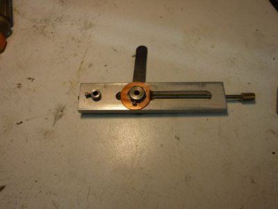
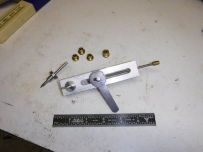
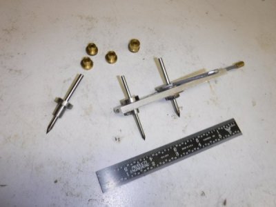
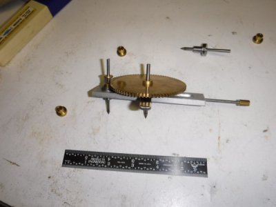
Apparently, as a clock maker, first you cut the wheels, then you determine the ideal center dimension between the two wheels. Then you transfer this ideal dimension to the workpiece. So to do this you need a depthing tool.
So, I made one, and here it is...
DSCF0100 (Large).JPG DSCF0139 (Large).JPG DSCF0140 (Large).JPG DSCF0142 (Large).JPG
When I tried to just hold the wheels in my hand and run them against each other, it seems like a pretty funky meshing. However, mount the wheels on the depthing tool you can definitely tell they mesh much better when they are held and turned in the same plane. Then you have to determine where the sweet spot is, i.e. where they mesh and spin without binding each other.
 
DSCF0103 (Large).JPG
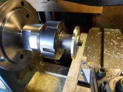
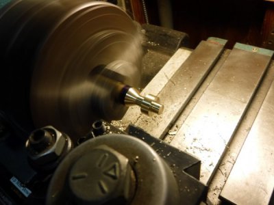
Above I'm checking the run out of the mandrel, before mounting some wheel blanks to turn to size.

DSCF0104 (Large).JPG
DSCF0105 (Large).JPG
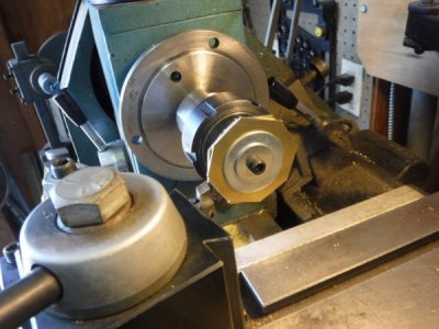
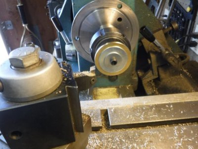
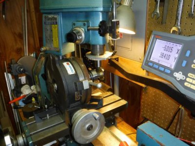
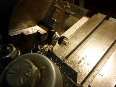
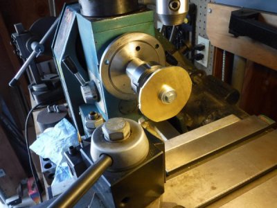
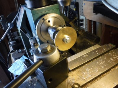
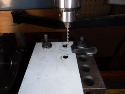
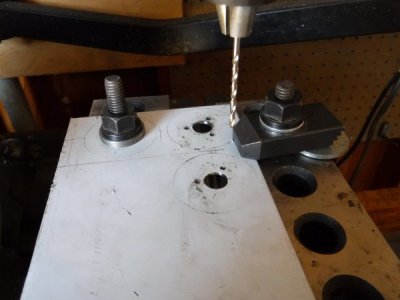
Below I am making the flanges that guide the wind cord over the drive wheel. I drilled and reamed the center holes first. Then I used the bolt circle function of my DRO to drill the holes for the mounting screws.
Then I rough cut them on the band saw before mounting on a mandrel and turning them to size as shown above.

DSCF0106 (Large).JPG DSCF0107 (Large).JPG

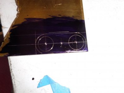
Below is the layout of the line cord stop
DSCF0108 (Large).JPG
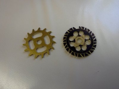
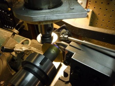
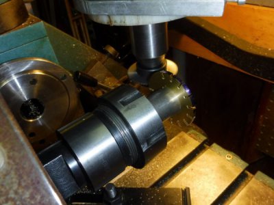
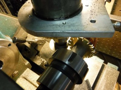
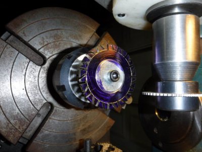
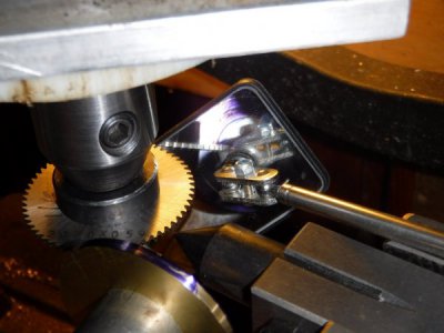
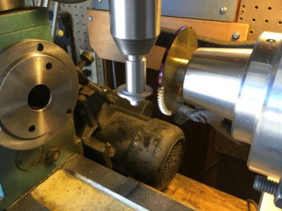
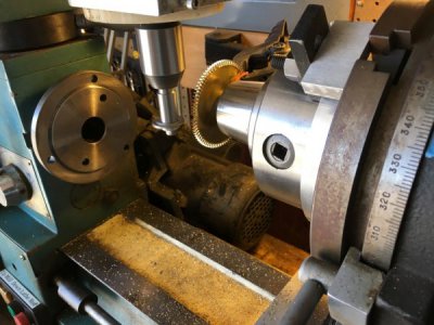
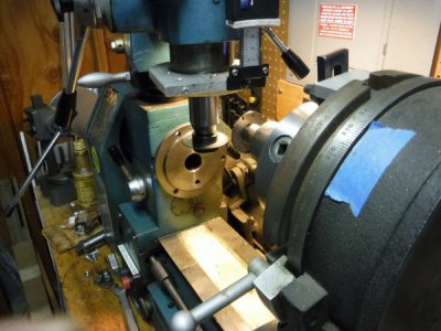
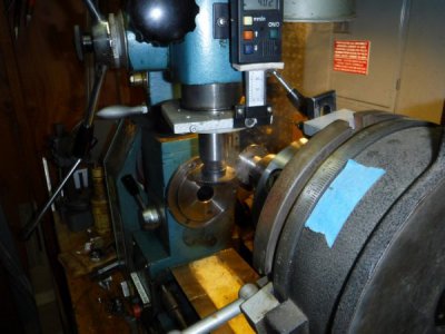
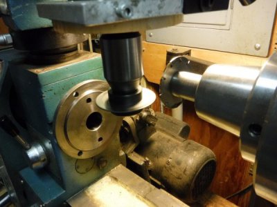
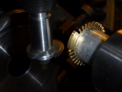
Below I am using a slitting saw to cut the ratchet wheel.

DSCF0109 (Large).JPG DSCF0110 (Large).JPG DSCF0111 (Large).JPG
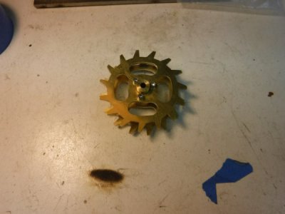
Below is getting ready to cut the teeth on the reverse minute wheel. The minute wheel is stuck to the mandrel with Loctite 603 because there is no way that little screw can hold on while cutting the teeth.
DSCF0112 (Large).JPG DSCF0113 (Large).JPG DSCF0114 (Large).JPG DSCF0115 (Large).JPG DSCF0116 (Large).JPG
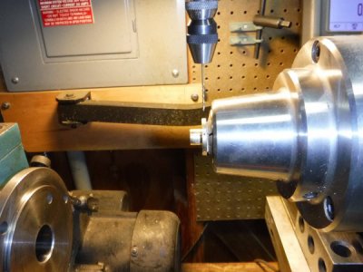
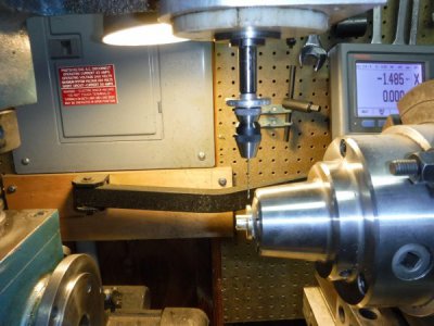
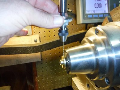
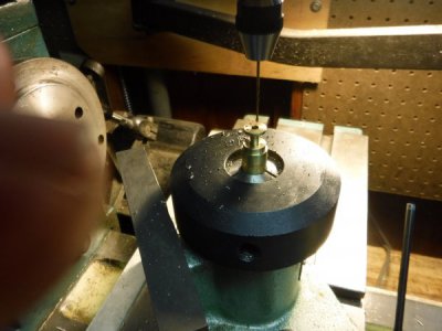
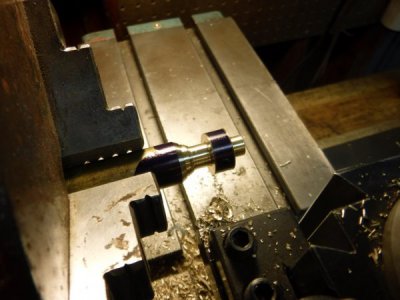
Below I'm cutting the radial holes in the ratchet hub. We will eventually press little pivot pins in the holes for the weight rope to drive the ratchet assembly. This little chuck has a micro feed collar that lets you use your fingers to start and drill holes. Perfect for these little drills.
DSCF0118 (Large).JPG DSCF0119 (Large).JPG DSCF0120 (Large).JPG

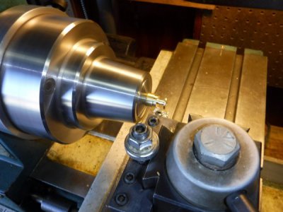
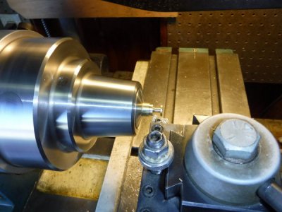
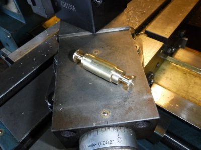
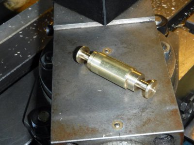
Below I am making the two little pinion gears.
DSCF0121 (Large).JPG DSCF0122 (Large).JPG DSCF0123 (Large).JPG DSCF0125 (Large).JPG

Drilling the holes for the pivot wire that will be pushed in to the pinion to form the "teeth".
DSCF0128 (Large).JPG
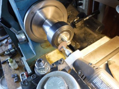
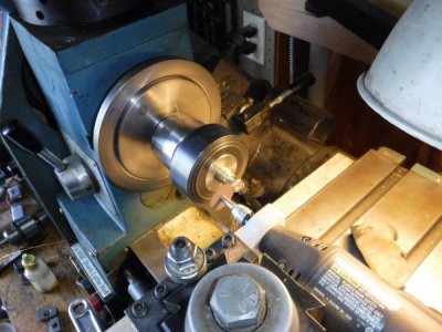
Below I am sawing off the pivot wires with my dremel mounted on the tool post.
DSCF0132 (Large).JPG DSCF0133 (Large).JPG
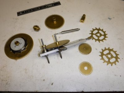
The pinion gears are in the picture below one is on the left side of the depthing tool and the other is sitting on the wheel that is immediately below my 6 inch scale.
DSCF0134 (Large).JPG
 
Back
Top