My LMS Mini Mill

Fabrickator

Active User
Registered
Joined
Jan 22, 2014
Messages
578
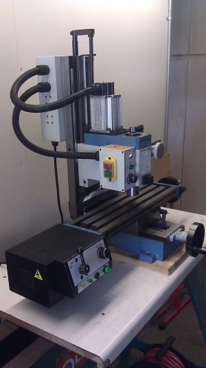
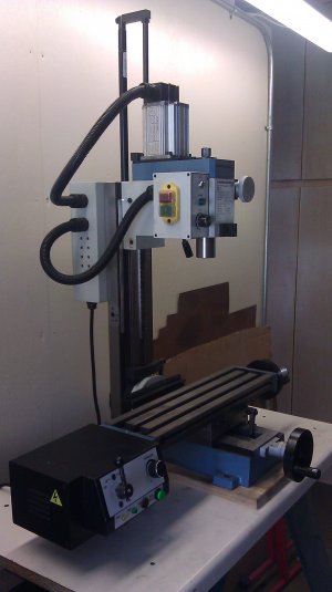
I decided to finally post the mods I made on my LMS Mill, even though it's a few year old now.

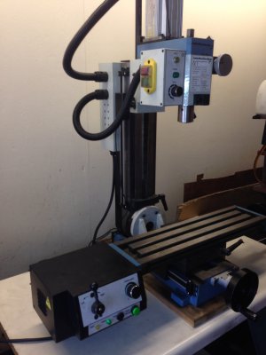
I ordered my mill with the power feed they offer, and installed it upon unpacking. I've been more than happy with the performance and I use it whenever I have the chance. It is a bit pricey, but I think that it's worth the cost unless you plan on going CNC in the future.

I also did the air spring conversion to get rid of the cumbersome torsion spring and make room for the DRO. It is also a great mod, very easy, reliable, clean and affordable.

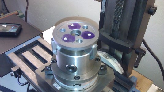
I also purchased the LMS rotary table and 3-jaw chuck and my only complaint is the depth it robs from the Z axis. While I had my mill apart, I did some R&D to see if I could find another few inches of Z axis because I've run out of room in the past trying to change out the drill/R8 collet with the rotary table/3 jaw. I discovered that an additional 1" is an easy task, but 2" are possible with a few more extensive mods. I'm still researching my options there, but I'll post it if/when I do it.

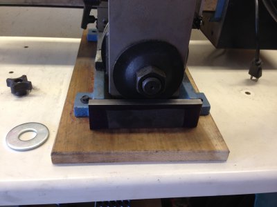
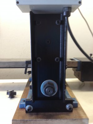
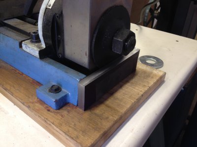
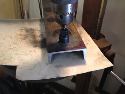
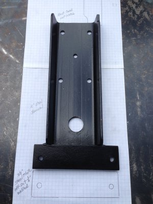
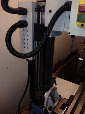
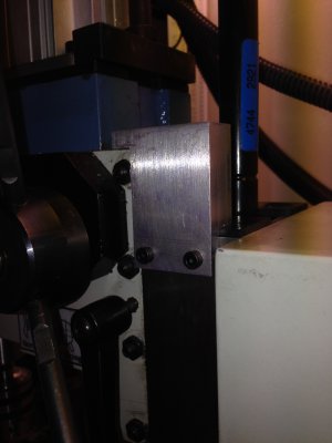
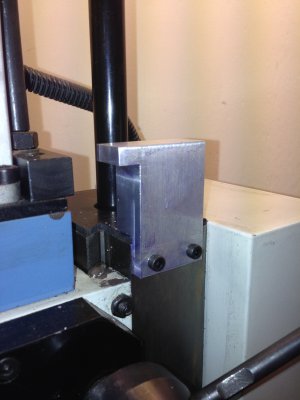
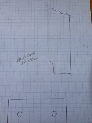
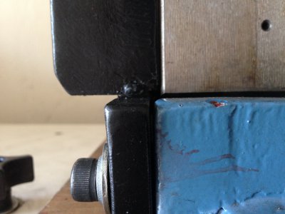
I then found that I got some chatter when trying to cut anything over .020" steel. I researched a lot of threads and found that the remedy was to add a stiffening bracket to the column. There were as many designs on the web as people posting them and so this is the design I came up with. 4" steel channel on a piece of 3/8" steel plate. Welded, drilled and mounted to the back of the column and then trammed. I read where some others were experiencing "head drop" and I found that I had to take a bit off the mill base because it wasn't let the new plate seat properly. After I did that, it trammed out fine.

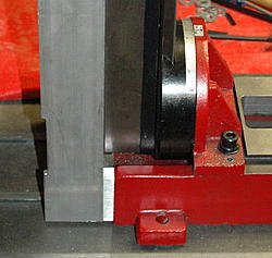
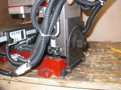
Note: Most of the threads on this subject are centered around the similar Sieg model and not the LMS. The Sieg column is designed/mounted differently in the base (or vice versa) than the LMS. In other words, the LMS column is set back inside the base by 1/8" and the Sieg is set out by about the same amount. Here are some pics of my bracket.

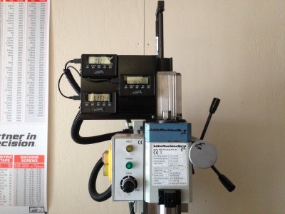
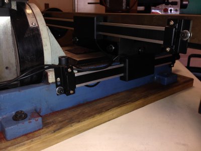
I also mounted the I Gaging DROs from Grizzly to all 3 axis and here some pics of my mod. Nothing to notable here other than I don't know I waited so long. I just recently installed them when they've been sitting around the garage for over a year now. It was after my last project (Elmer's #15) that I promised myself I'd get them done before starting any other projects.
IMAG0553.jpg IMAG0556.jpg IMG_0543.jpg IMG_0569.jpg IMG_0545.jpg IMG_0547.jpg IMG_0559.jpg IMG_0609.jpg IMG_0597.jpg IMG_0600.jpg IMG_0604.jpg IMAG0446.jpg
 
Call me Icona Pop, because I love it!! I can't wait for mine (and 60lbs of aluminum stock :p) to get here monday. How hard was it to install the DROs? I've been eyeing them but I'm concerned about drilling and tapping cast iron. The gas spring and power feed may also be added but that will be much later
 
I decided to finally post the mods I made on my LMS Mill, even though it's a few year old now.

Nice work..!

I have an Emco that has had a few modifications and improvements over the years, I might have cursed them as doing them but each one has paid off.

I'm sure your improvements will make your machine more pleasurable to use.:))
 
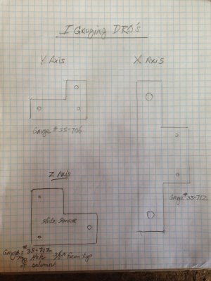
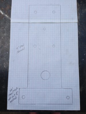
Icona Pop - Congrats on your new purchase. I'm sure you'll love it. The DROs require you making some brkts and drilling/tapping the cast iron is a breeze. I made a few pics of my brkts but took very few measurements. Although, it was on drafting paper (1/4" square type) so you may be able to transcribe them. Then after they're made and installed on the sensors, you could layout where to drill the mounting holes on the machine. I don't have them today and so I'd have to try to remember to take a pic tonight.

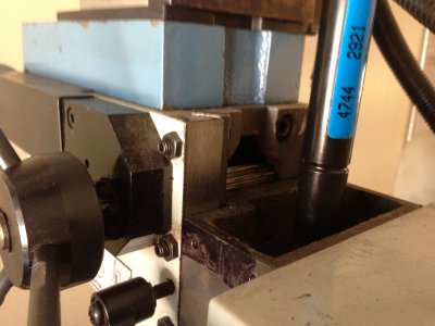
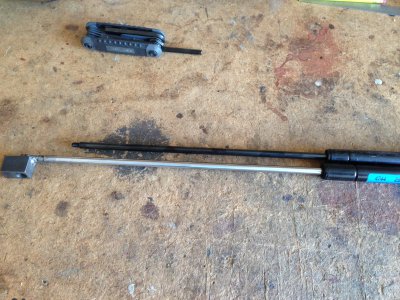
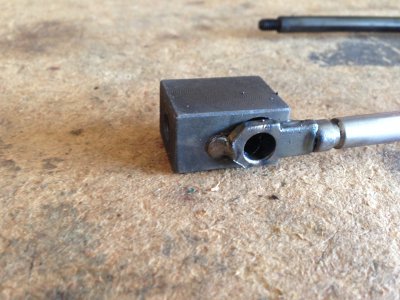
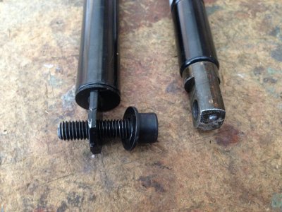
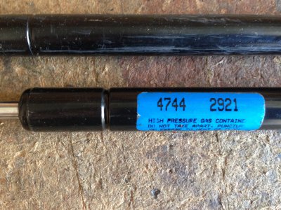
What I've noticed and several others have commented on with these mini-mills is the Z Axis can sometimes be restrictive. For me, its while I'm changing out my 1/2" drill chuck in tight quarters. I found a way to gain an additional 1 1/2" of travel w/o losing anything off the bottom. I researched a longer gas strut and found one that works. The only mods were to spot weld the LMS kit bottom boss on one end of the strut and make a new head stock "stop". This mod gives the LMS High Torque a full 12" of Z-Axis travel over the Std. LMS specs of 9.3".

The strut is for a mid-80-early 90's large GM hood support (Caddy, Buick, Olds). About $20 new, I found mine at a surplus house that I have nearby, used for $10. As you can see from the pics, anymore than 1 1/2" and you run out of "gear" to raise and lower the head stock. It still has 3 of the 4 gib screws securing it at the high end, so it's safe to do. I don't think that I would perform any heavy milling at this height, but I've never had a need to anyway.

http://www.liftsupportsdepot.com/value-10292w-strong-arm-gas-spring-lift-support-10292w/

IMG_0643.jpg IMG_0630.jpg IMG_0632.jpg IMG_0634.jpg IMG_0636.jpg
 
Here are the tracings of the IGaging DRO sensor brackets that I made for my LMS High Torque. The 1/4" drafting paper should help in creating the rough dimensions so you don't have to start from scratch. I used M-5 cap screws for mounting mine, but anything will work. All of the sensor mounting holes are the same (about 1 5/8"?) so you only have to figure that out once. My pics above are a bit dark but show the proper mounting positions to have full movement w/o any binding at the extremes of X, Y and Z Axis. I chose to mount the Y Axis on the high side (re-drilled) to still have clearance for the left-front mill base hole. All of the DROs were installed w/o disassembling anything. But, I do have a Harbor Freight Close Quarters Drill which helped on the Y Axis under the table.

http://www.harborfreight.com/38-close-uarters-drill-60610.html

I hadn't finished my head stock stop block yet when I first posted and so here are a few pics of it installed to complete my Extended Gas Spring mod. I later figured out that I also gained almost an inch at the bottom as well as 1 1/2" at the top (compared to the LMS gas spring kit) giving mine a total stroke of 13", which is a significant improvement over the LMS standard stroke of 9.3". :thumbsup:

Still to come:

Plexiglas cover/shields for X & Y Axis.

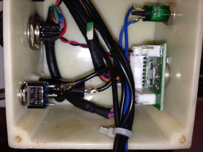
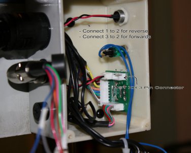
Forward and Reverse spindle control mod that I seen on another website. I installed the switch but haven't hooked it up yet.

Nice aluminum spindle handle and wheel knobs to replace the cheap plastic ones.

IMG_0651.jpg IMG_0656.jpg IMG_0618.jpg IMG_0654.jpg sx2_forwards_reverse.jpg
 
Re: My LMS Mini Mill - Cooling Fan

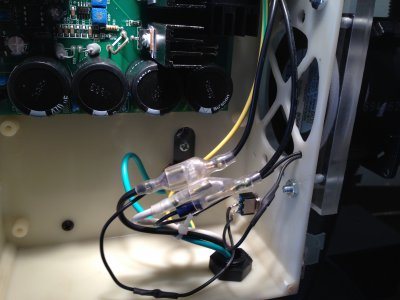
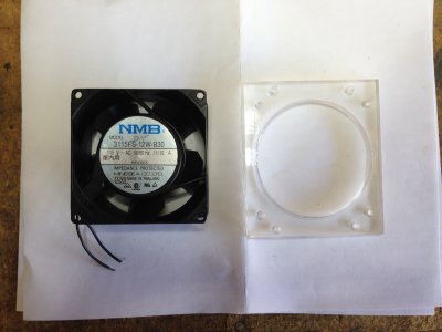
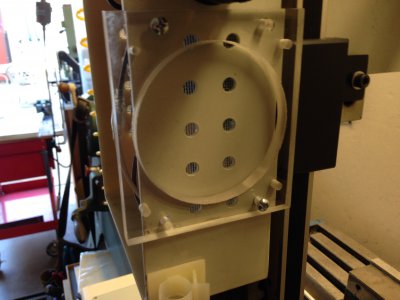
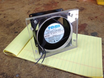
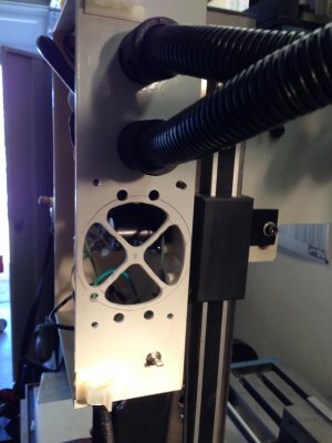
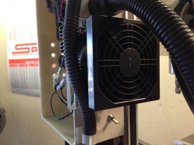
After reading another post where a guy fried his LMS Mill motherboard (possibly exceeding the duty cycle) I decided to take a proactive approach and install a 3" cooling fan that I had picked up at a surplus store for $5. I found that it was a pretty good fit on the side of the control box by simply making an adapter plate, installing a switch and tapping the power source. I used Plexiglas for the adapter plate because I thought that aluminum would just retain more heat. The plate covered four of the existing holes, but I cut in a full-face opening for the fan that nullified that issue. I also bought a snap-on fan screen/filter to ensure that nothing gets in there.

The fan draws in cool air from the opposite side creating a slight turbulence in the box that draws heat away from the heat sinks and other components. It's 115V, whisper quiet and pulls almost no amperage. I installed "piggyback" connectors on the main power cables and the existing connector boots covered them up nicely. It won't be necessary to run the fan all the time, but when working on a heavy cuts or for long duration's of time, it's cheap insurance.

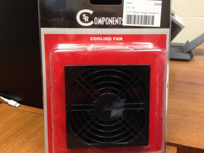
UPDATE: I popped over to my local electronics supplier and picked up the fan cover/filter for $5. Here's a pic of it installed.

IMG_0693.jpg IMG_0678.jpg IMG_0681.jpg IMG_0685.jpg IMG_0688.jpg IMG_0698.jpg IMG_0707.jpg
 
Last edited:
Why wouldn't you let it run all the time? Most cooling fans do and in the long term it's better.
 
Just not sure that it's necessary to run it all the time, but you certainly could.
 
I researched a lot of threads and found that the remedy was to add a stiffening bracket to the column. There were as many designs on the web as people posting them and so this is the design I came up with. 4" steel channel on a piece of 3/8" steel plate. Welded, drilled and mounted to the back of the column and then trammed. I read where some others were experiencing "head drop" and I found that I had to take a bit off the mill base because it wasn't let the new plate seat properly. After I did that, it trammed out fine.

Fab,

Could you provide some dimensions for your stiffening bracket. Am I correct that the big nut is off center?

Note: Most of the threads on this subject are centered around the similar Sieg model and not the LMS. The Sieg column is designed/mounted differently in the base (or vice versa) than the LMS. In other words, the LMS column is set back inside the base by 1/8" and the Sieg is set out by about the same amount. Here are some pics of my bracket.

I'm having a little problem understanding this. I have a Sieg X2. Maybe a little sketch would help.

Ken
 
Fab,

Could you provide some dimensions for your stiffening bracket. Am I correct that the big nut is off center?


I'm having a little problem understanding this. I have a Sieg X2. Maybe a little sketch would help.

Ken

Yes, it's off center by about 1/8". Don't ask me why...

I have a sketch on drafting paper if that would help you with getting some rough dimensions.

In you statement, "problem understanding" I assume that you are referring to the LMS base-to-column offset. The LMS column is negative (less than level to the base about 1/8") and the Sieg appear to be protruding about the same amount from what I've seen in pictures. That's why neither one can have a single, straight piece of metal to stiffen it w/o a dog leg or machining the base flat.

Look at these examples of some Sieg mods. Hope this helps.

IMG_0561.jpg IMG_0563.jpg IMG_0589.jpg column%203.jpg column%20rear%20support%201_800x600.jpg
 
Back
Top