Thank you for the swifty and warm welcome!
Maybe it would help if I posted my first question.
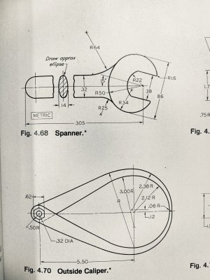
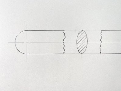
The first one is in the picture fig. 4.68. It is in METRIC. In what sequence of setting off measurements do I locate the center of R34?
Here is my sequence:
- draw center line
- set off two lines 16mm from each side of centerline
- with compass use the 16mm as a radius. close end of handle
- from end of handle to center point of R22 and R50. strike both arcs
- at 15 degrees from centerline and with centerpoint being R22 and R50 pulled 2 parallel lines 43mm from center. These are the outermost (apex) points of the 15 degree tilted ellipse. I also draw parallel lines 19mm from center.
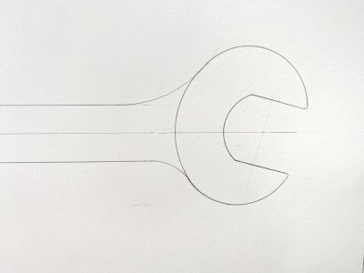
- Here is where I'm unsure how the center point for the arc with R34 is located. And how does the curvature from R50 and R34 resolve? Do I use an irregular curve to connect these two radii?
Thanks for any help!
First off, welcome to the group!
I don't know anything about drafting, but looking at the drawing, it appears to me that the
R34 and R50 radii "change over" at the point that R25 intersects them. It doesn't seem
that you need to resolve it in the sense of a gradual change. I would draw R50, then R25
and then R34. As for R34, it looks as though the lower line that defines the 86mm width of the
spanner could be used as a tangent line. Draw a 34mm line 90 degrees to it, find the center point,
and draw the arc. Actually, it looks like you would have to do that twice for the upper and lower radii.
How's that for a completely uniformed opinion?
My son just started class for a one year Solidworks certification program. One of his classes started
the students out with manual drafting. He has some art background as well, but he told me he likes
the drafting because it satisfies his OCD.
")
(which he actually doesn't have...)