NSFW My Oliver S-1 Die Filer finally made it! BUT, UPS had their way with it.

Warning: thread may contain photos that are not for the squeamish.
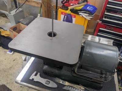
While waiting on the power feed on my mill to clean up a block of aluminum for another project, I decided to break down the die filer to see how much work it'll be.

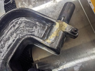
The motor bracket looks like it /the motor aren't made for it, and someone added two bolt holes to hold down the bracket.
PXL_20230113_233528034.jpg

As you may remember, the motor fell off the bracket during shipping. It was damaged by "spreading outward" to the point the motor no longer lined up. SO I pulled it off, cleaned it with some WD40 and a shop towel, and put it on the arbor press. I was able to bend it back just about perfect:

PXL_20230113_234224358.jpg

I'm still going to rewire the motor/do something different with the switch, but at least it mounts correctly.

The table was held on by a single T bolt/nut combo:
PXL_20230113_234546114.jpg

The underside of the table looks in really good shape, just dirty. Everything seems right! I'll end up cleaning this better when I put the machine back together. Though, I have no idea what those three holes on the far side are for...
PXL_20230113_234745352.jpg

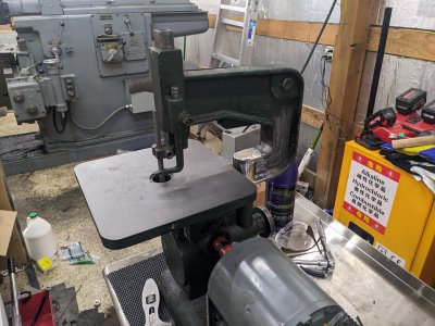
The body bolts with 3 bolts to the base. The annoying part is 1 was too close to the edge to use a socket in. It came off easy enough anyway.

One nice thing, the bottom of the shaft/bearing is enclosed! This means it shouldn't leak too bad.

PXL_20230113_235356347.jpg

And, removed:
PXL_20230113_235659153.jpg

Next, I removed 4 REALLY tight and buggered screws for the main case face:
PXL_20230113_235925097.jpg

I drained the oil, but it looked like pretty new motor oil, some heavy viscosity. The REALLY nice part is the inside is nice and clean, and tight. I thought I'd have to tear this down and replace a bearing somewhere, but there is zero play on anything!

I think I'll make a gasket for the face, oil it, and run it as is.PXL_20230114_000553313.jpg

The outside itself needs a good clean, and had a mediocre paint job in it's past. I'll likely just hit it with a wire wheel enough to clean it, but probably not enough to paint it, depending on how well the paint survives cleaning.

Overall, I'm hopeful that once the welder has his way with the arbor support, this won't be too much work to put back in service.
 
I spent the afternoon doing a bit of cleanup. Just simple-green + WD-40 + some brushes and a wire-wheel for some of it.

I opted to leave the paint as it is the best I could, though I noticed THREE different coatings! There was a Japaning, that I originally thought was just gunk. There was a light grey, and the green. The green is obviously the most recent (and was done less-accurately, since they got bolts, data plates, etc. I ended up making a rubber/paper gasket for under the main body, plus used copper washers, since the bolts go through. I also made a new paper/rubber gasket for the main cover, and filled with some gear oil I had around.

PXL_20230116_232925847.jpgPXL_20230116_232931172.jpg

It cleaned up nice! I also re-wired the motor with a nicer cord, though I haven't wired in the switch or speed controller yet, that might be tomorrow's task.

WHILE I was trying to clean the table, I noticed that it was FAR from flat. It was pretty divoted/dished out, so I went over to the shaper to try to clean it up. After a first pass, which was probably only ~5 thou, this is what it looked like:

PXL_20230116_230807855.jpg

A little worse than I thought it would be, but another 10 thou got me to:

PXL_20230116_232703549.jpg

ANOTHER 10 thou pass got me to:
PXL_20230116_235609653.jpg

That last little bit (and I didn't quite get it all!) took another 25 thou after those, but its nice and smooth, plus VERY flat!

PXL_20230117_003631056.jpg


I got a chance to fire it up, and discovered why people complaint it is a finger pincher. My fingers weren't pinched, but the material was definitely pulled upward frequently. I can't wait to get the overarm to help keep that from being a problem :)

Either way, its a nice machine that sounds and looks to be in great shape!
PXL_20230117_004716331.jpg
 

Attachments

  • PXL_20230117_004716331.jpg
    PXL_20230117_004716331.jpg
    431.1 KB · Views: 8
Wow, that take was a long way out of flat!
Yeah, I was pretty shocked to say the least! It DID seem like pretty soft cast iron, so perhaps just years of use wore it out! Though, I imagine it was only somewhat flat in the first place :) Either way, its about as flat as it gets now.
 
discovered why people complaint it is a finger pincher.
Yep, that was a big surprise to me when I started using the Butterfly filer. I made an attachment gizmo with a couple fingers to hold material, it works ok but probably needs a design iteration or two. The initial thought was to make it pretty adjustable and preserve visibility of the work. Seems OK at that.

You can see in the picture a roller arm that can be swung around as a file guide for longer files.

1674053683197.jpeg
 
Nice! Yeah, the overarm support has something like that built into it, but i don't have that back from the welder yet.
 
A 2 hr, $190 job, but the over arm support repair is done! From the looks of it, he brazed it back together (one of the options we discussed), and IMO, it turned out pretty darn good:


PXL_20230119_214846945.jpg

PXL_20230119_214856012.jpg
PXL_20230119_214842820.jpg


I assembled it, and it seems to line up just right, and runs good:
PXL_20230119_215212254.jpgPXL_20230119_215633999.jpgPXL_20230119_215637265.jpg


I DID pull the side off though, and discovered the overarm needs some attention, so I probably have this to do next. I was actually surprised how much was going on inside here.

PXL_20230119_215627681.jpgPXL_20230119_215342516.jpg

So, my TODO list:
1- "Unstick" the foot, and perhaps re-make it. It is stuck in place, and looks like the file hit it a few times :D I might just leave it as-is.
2- Strip, clean, paint the overarm. Its all pretty crusty, so a wire brush and some elbow grease should clean it up nicely. The brazing required removing paint, so replace that too
3- Make a 'zero clearance' insert of some sort.
4- Re-make the 'clamp' part of the overarm. That tiny little file was enough to put me at only 1 thread on the nut holding the clamp on, so I likely should make a new one with a longer threaded rod as a part of it. Easy enough job, but something that needs doing!
5- re-make the overarm 'position stop'. Its currently a flat head set screw with a lock-nut, but the flat head part is basically busted. So replacing it is likely a good idea.
 

Attachments

  • PXL_20230119_214852835.jpg
    PXL_20230119_214852835.jpg
    485.7 KB · Views: 14
  • PXL_20230119_215208179.jpg
    PXL_20230119_215208179.jpg
    495.1 KB · Views: 13
The person that did that looks like they really know what they're doing, looks like an excellent repair
 
The person that did that looks like they really know what they're doing, looks like an excellent repair
Absolutely! Despite being a welding shop owner in a small-town, he's quite skilled! I was really impressed with his work! He has helped me out at least 1x before (when I tried to take my mill home, and the pallet it was on collapsed, he sold me a cheap sheet of 1/4" steel plate, plus used his forklift to lift it off the pallet/onto the plate, charging nothing for the labor!). He gave me what is likely a pretty good deal here (that much work for only 2 hrs of labor!) despite it being a pretty challenging fix, AND kept everything lined up just right!

Today in the shop, I spent a bit of time trying to clean this up and make some replacement parts for it.

First, I tore down the overarm support. The inside was caked with a little surface rust, plus a bunch of grease. The simple green + a wire brush + a dremel wire brush cleaned everything up quite nicely! The welder had to take off a bunch of the paint, plus the inside was pretty unpainted, so I started that as well. The clockworks seemed to be in great shape however!

PXL_20230120_220315901.jpgPXL_20230120_220720565.jpgPXL_20230120_225053339.jpg


Next I made what is essentially a zero-clearance insert. This was a bit of an adventure due to my inability to pay attention today, but started with a hunk of aluminum, then turned the two diameters:

PXL_20230120_225100681.jpgPXL_20230120_231004155.jpg

Note I'm using a 4 jaw because I'm too lazy to swap over to my other chuck, and was going to need this soon anyway. I snapped my parting blade parting this off, so I got to go to a scrap/pretty dull/old one to finish it off. It was a bit scary when the parting blade snapped, but everything ended up in the chip tray i think.

Then, I flipped it, and faced it to dimension:

PXL_20230120_232527582.jpg


I put a bit of an 'eased' chamfer on it, and it turned out pretty good! Its about 3-4 thou below the surface in the center, which seems about right.

PXL_20230120_233144421.jpg


Next, I wanted to work on the overarm's clamp. I found this scrap of unknown steel. Its not CI based on how it cuts, but I'm guessing its a particularly awful type of hot-roll. I put it in the mill and popped a center in with the DRO after facing it:

PXL_20230120_233913895.jpg

I used this to get it lined up more or less in the lathe (I did a poor job, but in the 'right' direction). In retrospect, this was a job for blue + height gauge + a center punch, but I didn't think of it at the time and thought I would indicate it in, before realizing that was a waste of time.

The interrupted cut made my cutter REALLY unhappy with .150 DOC cuts, and the chatter was unbelievable. BUT, when the interrupted cut ended, we were fine. The joys, and scariness of a big lathe, you'll be able to take stock down really quickly, but you'll break tooling/bend parts just as quickly!

PXL_20230120_235011473.jpg


Then, I turned a 5/16-18 spot on the end, which will be how it bolts in. Next I have to mill the profile down, but thats a job for next time:

PXL_20230121_003608683.jpg


All 5 remaining sides need milling, though only 1 is critical in any way.
 
Back
Top