
Head alignment, in my personal experience, isn't a huge deal and doesn't need to be perfectly square when you first set it for a job. However, once you've set it, it does need to stay for the duration of the job. So when you first set it make sure your longest and your shortest tools can reach and you have room to change them too, the z fine feed can move about 5 inches on mine and that's usually enough for a job. The collet system helps with this too as your can change the bits and keep the lengths similar. However, there are times when you do need to move the head and while there are several methods to keep the head in alignment I find this one the best for its simplicity. Hope that helps.

-
Welcome back Guest! Did you know you can mentor other members here at H-M? If not, please check out our Relaunch of Hobby Machinist Mentoring Program!
You are using an out of date browser. It may not display this or other websites correctly.
You should upgrade or use an alternative browser.
You should upgrade or use an alternative browser.
My round column RF30 mill to CNC conversion, the cheap way
- Thread starter stioc
- Start date
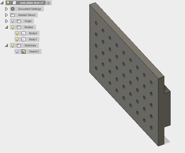
Made a fixture plate with dowel-pin holes as well as threaded screw holes. The plate can be mounted in the vise or directly to the table. . As usual ran into a couple of issues but managed to overcome them. This was a few different operations.
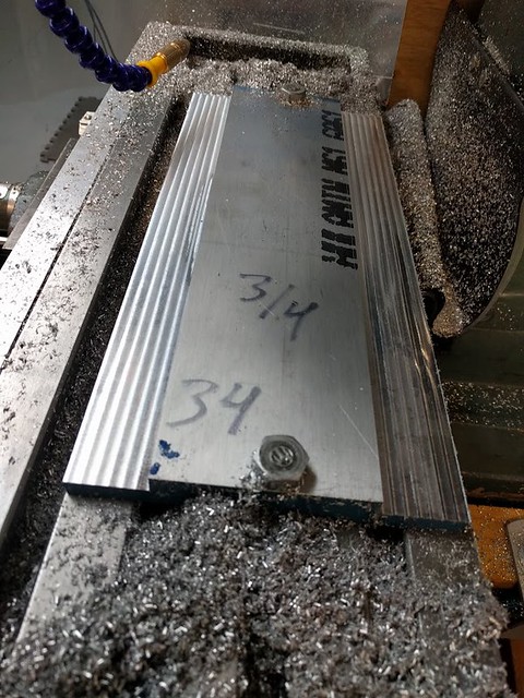
Millng: I started with milling the shoulders. Unfortunately this is where I ran into the biggest issue- unbeknownst to me the TTS collet holder worked itself down out of the TTS R8 adapter, likely because of my heavy cut (.25" DOC using a .25" roughing mill). This made the shoulders uneven/crooked So once I tightened it well I had to take several passes to get the shoulders to be flat again.
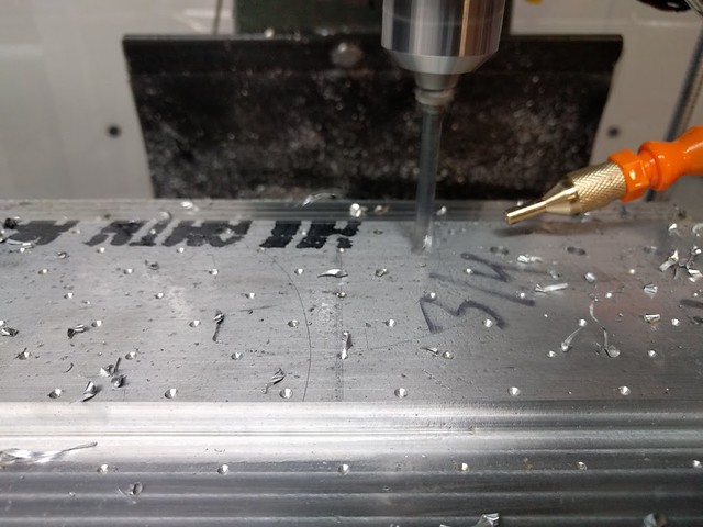
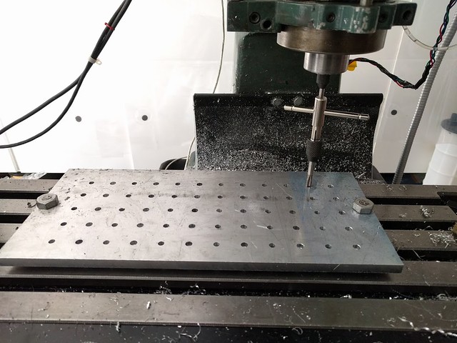
Drilling: I was a little worried about the feed rate (plunge rate I guess) but 7ipm worked great using chip breaking and pecking at .4". Except I did this on top of a piece of plywood and despite the alum plate being 3/4" thick it bowed in places because when I flipped the plate over the drill bit had only broken through a couple of the rows.
Drilling after spot drilling:
Top side of the fixture plate with only two rows of actual holes
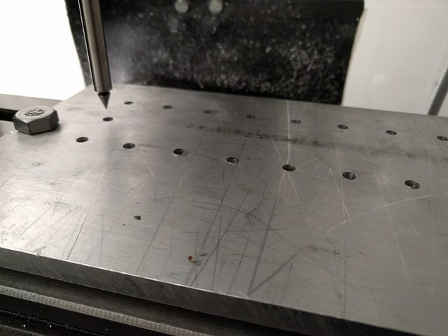
Since I'd already lost my 0,0 on the x/y I decided to drill from the other side (top side). Oh and I lost my 0,0 because the plate is almost as long as my x-axis travel (14") so I had to fudge it a little to get started.
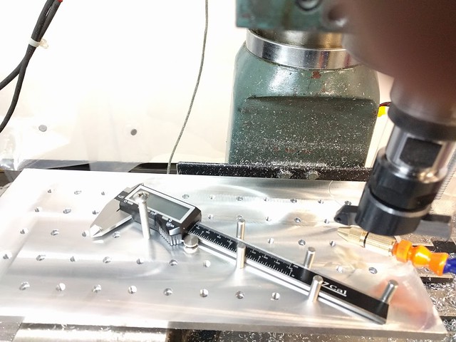
Honestly I had to think about how to do this (drilling from the other side and meeting the hole half way). Now I'd never used the wiggler center finder before, nor did I really know what it was for until I had the eureka moment. So as shown in the pic above I found the center of a specific hole, then used g91 (relative move) backward to 0,0 (e.g. g91 g0 x-1.45 y-1.134) then touched off to reset G54. Now I'm sure everyone probably knows or uses this trick but I felt like a genius that it actually worked :thumbup:
Tapping 30+ holes: I don't have a tapping head nor is my spindle cnc controlled so again using a little bit of thinking I came up with a hybrid solution. I'll use the CNC to guide me to each hole and then I'll use the spring loaded tap guide to help me thread the first 4 or 5 turns. After that I'll power tap using my hand drill. So I took the drilling g-code and removed all the z axis stuff and after every x,y move I added m6 t1 and m6 t2 (alternating it) so that after each move the machine waited for me to "change the tool" but in reality it just paused the motion so I could hand tap the first 4 or 5 turns then hit continue and do the same thing for all the rest of the holes.
Worked like a charm! :thumbup:
All in all I enjoyed building it and with each bump along the way I feel like I'm starting to find ways around the challenges
Millng: I started with milling the shoulders. Unfortunately this is where I ran into the biggest issue- unbeknownst to me the TTS collet holder worked itself down out of the TTS R8 adapter, likely because of my heavy cut (.25" DOC using a .25" roughing mill). This made the shoulders uneven/crooked
So once I tightened it well I had to take several passes to get the shoulders to be flat again.
Drilling: I was a little worried about the feed rate (plunge rate I guess) but 7ipm worked great using chip breaking and pecking at .4". Except I did this on top of a piece of plywood and despite the alum plate being 3/4" thick it bowed in places because when I flipped the plate over the drill bit had only broken through a couple of the rows.
Drilling after spot drilling:
Top side of the fixture plate with only two rows of actual holes
Since I'd already lost my 0,0 on the x/y I decided to drill from the other side (top side). Oh and I lost my 0,0 because the plate is almost as long as my x-axis travel (14") so I had to fudge it a little to get started.
Honestly I had to think about how to do this (drilling from the other side and meeting the hole half way). Now I'd never used the wiggler center finder before, nor did I really know what it was for until I had the eureka moment. So as shown in the pic above I found the center of a specific hole, then used g91 (relative move) backward to 0,0 (e.g. g91 g0 x-1.45 y-1.134) then touched off to reset G54. Now I'm sure everyone probably knows or uses this trick
but I felt like a genius that it actually worked :thumbup:Tapping 30+ holes: I don't have a tapping head nor is my spindle cnc controlled so again using a little bit of thinking I came up with a hybrid solution. I'll use the CNC to guide me to each hole and then I'll use the spring loaded tap guide to help me thread the first 4 or 5 turns. After that I'll power tap using my hand drill. So I took the drilling g-code and removed all the z axis stuff and after every x,y move I added m6 t1 and m6 t2 (alternating it) so that after each move the machine waited for me to "change the tool" but in reality it just paused the motion so I could hand tap the first 4 or 5 turns then hit continue and do the same thing for all the rest of the holes.
Worked like a charm! :thumbup:
All in all I enjoyed building it and with each bump along the way I feel like I'm starting to find ways around the challenges
Last edited:
Thanks Tom. It's 13.9" x 6.2". The hole spacing is 1" and every other hole (on the X plane) is counter-bored .25" with a 1/4" drill-bit for the dowel pins.
I should mention that the dimensions weren't of my choosing, I happened to find a 3/4" plate off-cut at the metal shop which cost me $10 or so. I was originally thinking of making a bigger fixture plate, about 18x8 or so but I think this will work fine especially since I can hold it in my 4" vise which allows me to leave the vise in instead of having to remove it and remount it for different types of work. I also noticed someone out of east coast is selling them on ebay in various sizes, just as another option for anyone interested.
I should mention that the dimensions weren't of my choosing, I happened to find a 3/4" plate off-cut at the metal shop which cost me $10 or so. I was originally thinking of making a bigger fixture plate, about 18x8 or so but I think this will work fine especially since I can hold it in my 4" vise which allows me to leave the vise in instead of having to remove it and remount it for different types of work. I also noticed someone out of east coast is selling them on ebay in various sizes, just as another option for anyone interested.
- Joined
- Feb 27, 2014
- Messages
- 2,129
No need to answer my question about PECK in the other thread. I had to work on a part that was just slightly larger than my X travel so I milled a small slot near the center that did not interfear with the design of the part and I use that to zero the part. I could do the Left of the slot then move it and do the right of the slot. I could turn it over and do the the same thing. Very handy as long as you have or can add a feature near the middle with a flat in both the X and Y planes. I also find that when I am drilling thru holes, It works out best to specify a hole depth .01 to .005 deeper than the material to get a good clean hole.
I already replied to your question in the other thread lol Doesn't hurt, there might be someone else wondering the same thing.
I did use -.05 from bottom of the hole, I guess the plywood was quite distorted? I want to say I've had better luck with MDF.
That's a neat trick about having a scribe or something to split a large work piece in half (or more). So when you slide the work piece over to do the second section you somehow keep it square too in the y plane too right? like by using a square as a stop against a known location on the table?