My round ram M-head Bridgeport refurbish project

quality parts

H-M Supporter - Gold Member
H-M Supporter Gold Member
Joined
Sep 15, 2019
Messages
19
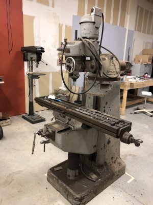
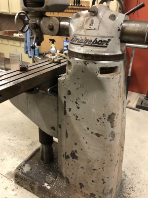
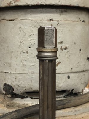
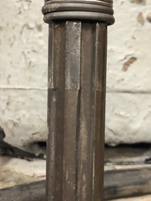
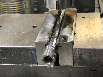
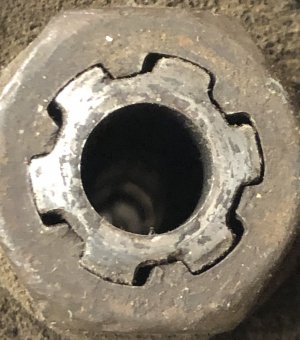
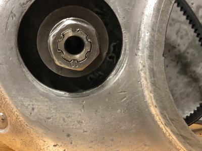
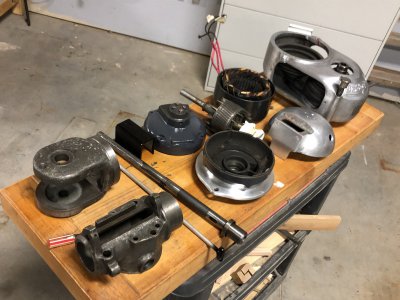
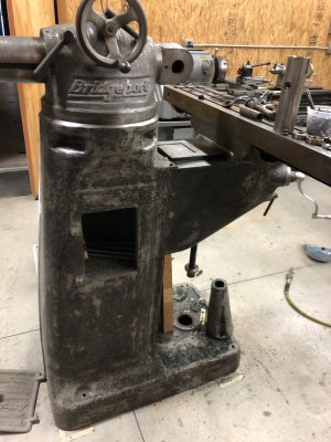
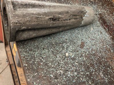
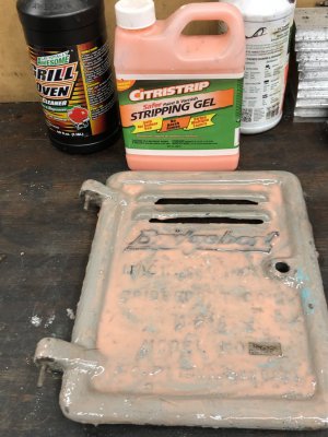
I bought this Bridgeport along with a decent LeBlond dual drive from an estate a few months ago. At first I was just going to get rid fo the Bridgeport but as I realized it was mostly complete I decided to clean it up and use it in my hobby shop. Its main problem areas were the terrible paint job, lots of surface rust from being seldom used and in an unheated shop for many years, the spindle and hub splines badly worn, motor and spindle bearings dry and worn out, and the quill feed not being properly assembled. Of course the ways are worn some but once I flushed out the grease and got way oil in them they move fairly smooth. It will never be cherry but I think it will make a suitable hobby machine unless or until I get into a project that requires a nicer mill. Besides I needed a project so here goes.
 

Attachments

  • 4D125576-8F13-4C82-B532-31F67294BC65.jpeg
    4D125576-8F13-4C82-B532-31F67294BC65.jpeg
    232 KB · Views: 29
  • 210FE7A7-E65B-4D51-86EE-10FEE1BF0D20.jpeg
    210FE7A7-E65B-4D51-86EE-10FEE1BF0D20.jpeg
    279.4 KB · Views: 28
I actually started on this teardown a few weeks ago, so some of the work is already done and I will report the steps I have completed. I needed to use the mill for a few small projects so I wired it in and got it working, replaced the vise grip knee crank, and did some basic cleaning. Then started scraping multiple layers of paint off of everything. The serial number puts it about 1948 vintage so the first color looks to be that blue/green color from that era and several gray layers applied poorly after that. One of the projects I needed the mill for was to build fixturing to repair the splines on the spindle. The original M-head spindle has a 7/8-20 LH thread on its top where the draw bar attaches. This machine had that threaded portion completely cut off along with the top 3/8" of the drive splines. Also the splines were badly worn probably from running it dry while drilling deep holes sometime in its past life. My plan was to build up the splines with weld and machine new grooves to match the worn hub splines.
 

Attachments

  • 2874040E-FA75-4C98-86B3-99F76D7F69F3.jpeg
    2874040E-FA75-4C98-86B3-99F76D7F69F3.jpeg
    205.7 KB · Views: 13
  • 6EDF8448-5654-46F6-939A-0E5297142BAD.jpeg
    6EDF8448-5654-46F6-939A-0E5297142BAD.jpeg
    187.6 KB · Views: 12
  • 0FDB3F47-FA2E-4D28-A44F-C8A260C293A1_1_201_a.jpeg
    0FDB3F47-FA2E-4D28-A44F-C8A260C293A1_1_201_a.jpeg
    240.4 KB · Views: 13
My welding skills (lack thereof) are on display but I was able to add material to the worn areas and add the threaded top for the draw bar attachment. I only welded one side of the grooves so I could use the unworn unwelded side of each groove to index the spindle to remachine the grooves. The spindle warped a bit and I was able to straighten it pretty close in the press. Then put it back in the lathe and turned the welds down to diameter.
 

Attachments

  • F69D2EAA-6281-4CF5-B557-A4B8B2DC8423.jpeg
    F69D2EAA-6281-4CF5-B557-A4B8B2DC8423.jpeg
    499.4 KB · Views: 18
  • 1C2623A1-00F1-491A-B10B-A4BDA00E1866_1_201_a.jpeg
    1C2623A1-00F1-491A-B10B-A4BDA00E1866_1_201_a.jpeg
    367.5 KB · Views: 17
I borrowed a friend's mill to machine the grooves. The special vise jaws fixture the spindle and allow me to index it accurately for milling each groove. Because of the excessive wear on the hub, the grooves needed to be somewhat narrower than the original splines and the grooves have to pass completely through the threaded portion of the spindle. A little more straightening in the press and I was able to get less than .002 TIR runout at the top of the spindle so decided this is as good as it will be. Hopefully when I reassemble everything it will work smoothly. I expect that it will wear some because the weld is probably not as hard as the original spindle, but this should be OK for the light use in its future. The spindle and hub are not available new, so repair was my only option until I find a good used one.
 

Attachments

  • FEF257D7-B3B2-4D3A-B13D-29B72223B7DF.jpeg
    FEF257D7-B3B2-4D3A-B13D-29B72223B7DF.jpeg
    185.3 KB · Views: 21
  • A771CB31-BD23-45C4-B3D9-B6CEED8A2FDE.jpeg
    A771CB31-BD23-45C4-B3D9-B6CEED8A2FDE.jpeg
    215.7 KB · Views: 20
  • EEAE243F-928F-416B-84A9-055ED4AA00DF.jpeg
    EEAE243F-928F-416B-84A9-055ED4AA00DF.jpeg
    414.2 KB · Views: 21
Was that stick welding? Looks pretty good
What type of rod?
 
Yes, stick welding with 7014 rod, DC. I don't remember whether DCEP or DCEN. I tried for less penetration and taller bead. Maybe should have used a little bit smaller rod too. All in all I think it will work out OK for my use. The pictures show the top view of the hub and spline before and after the repair. The clearance now is real small but before repair it was about .020 in the top part of the spline and somewhat more in the badly worn area. The rattling when using an end mill was pretty bad.
 

Attachments

  • 0FDB3F47-FA2E-4D28-A44F-C8A260C293A1_1_201_a.jpeg
    0FDB3F47-FA2E-4D28-A44F-C8A260C293A1_1_201_a.jpeg
    240.4 KB · Views: 20
  • 1B13CBF2-8AD4-448E-806A-90A0833CC099.jpeg
    1B13CBF2-8AD4-448E-806A-90A0833CC099.jpeg
    408.5 KB · Views: 20
Yes that was quite a bit of wear- you see people in other countries doing this kind of repair all the time
where it's either fix it or toss it- and they almost never toss it
One guy even welds crankshafts back together which amazed me
 
I've been scraping paint for several days. I scraped a little each day as it is strenuous and I am only good for an hour or so. Meantime I have cleaned up several parts and painted the motor, waiting on all the new bearings to assemble the motor and quill. Today I finally finished up all the paint removal and have started cleaning up the knee and column castings for paint. i do not plan to remove the knee for cleaning. This machine will never be in a museum or a serious machine shop.
 

Attachments

  • 4F4EE6CA-E3C5-4710-B9BB-DB3829C6F9EF.jpeg
    4F4EE6CA-E3C5-4710-B9BB-DB3829C6F9EF.jpeg
    401.9 KB · Views: 15
  • 4B63AEF5-C7E9-49B7-8DC8-2F00FE7335E6.jpeg
    4B63AEF5-C7E9-49B7-8DC8-2F00FE7335E6.jpeg
    291.4 KB · Views: 14
  • F38226BC-07AD-4AA1-B372-BCE9BAE6AE49.jpeg
    F38226BC-07AD-4AA1-B372-BCE9BAE6AE49.jpeg
    758 KB · Views: 14
This is the end of the ram where the head adapter attaches and allows the head to pivot up or down. Notice the little copper pieces inset into the casting machined surface. Can anyone school me on the purpose of those inserts? They are flush with the surface and I don't plan to do anything with them. Just curious about their purpose.

Mark
 

Attachments

  • 7B431E3F-A32A-407E-A027-62AB9754DA23.jpeg
    7B431E3F-A32A-407E-A027-62AB9754DA23.jpeg
    395 KB · Views: 14
I have been busy stripping paint and cleaning the castings for paint. The bronze side door had several thick layers of paint so I decided to use chemical stripper. This worked better than I expected and nearly all the paint was easily removed after letting it soak all day.
 

Attachments

  • 778F9EB6-52B1-4BAE-A82B-541D257BB01A.jpeg
    778F9EB6-52B1-4BAE-A82B-541D257BB01A.jpeg
    264.7 KB · Views: 5
  • 4C6D3FE1-5D17-43BB-A643-F6A566DFE38F.jpeg
    4C6D3FE1-5D17-43BB-A643-F6A566DFE38F.jpeg
    345.2 KB · Views: 5
Back
Top