Mystery Project...

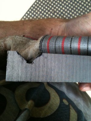
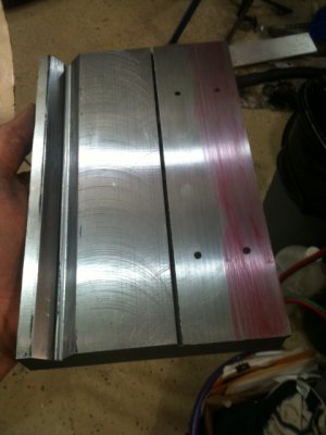
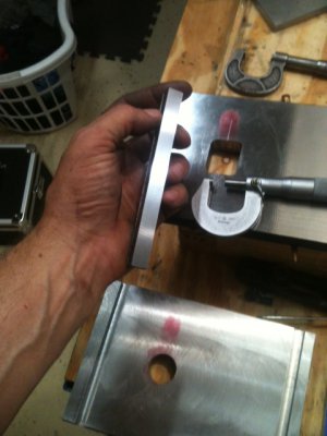
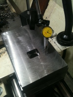
After hitting the other side of the grove with the surface grinder, now I'm fitting the V-groove. Before doing anything, I ran a file over the ground surfaces to get rid of some chatter marks. The wheel I "sacrificed" to put a 45[SUP]o[/SUP] angle on is an extremely hard wheel -and hard wheels chatter like crazy. The initial fit was quite good with no wiggle but needed a good bit of tweaking. I checked flatness of the bed plate with a DI mounted on the crossfeed and then I discovered the v-groove had to be cut a little deeper -back to the SG... With all said and done and a little tweaking it's at about 1 thou from side to side. To fix that, I'll need to take a tiny bit off the flat side of the of the bed plate.

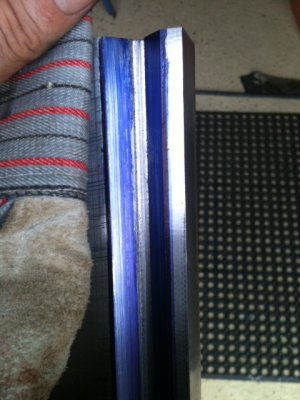
Right now, I'm bluing the all the V's and checking for rub spots. Here you can see some as well as the profile with a top-slot cut in at the root. Later on, I'll put an oil cap on the top side.

Now I know I'm dangerously in "scraping territory" here and I have no clue other than watching Rich's DVD but, this is coming along well. I'm sure you pro guys would just as soon get a rope and hang me but, I took a HSS lathe bit, ground it to serve my needs and pounded a wooden block on the end for a handle. It works-out pretty well. I can go right to those high spots and peel the tops of e'm right off. After that, I hit it with a file, slather with more bluing and try again.

It's a slow process and has taken me 2 hours so far (and about 20 test fits) but, I'd say it's probably 80% of the way there. At some point, I'll have to put some feather-scraping in there for oil... -I'll figure that out when I get there.

Oh, BTW, you can see that Sash thinks this is a very, very boring process. -Poor girl, she hates when I sit for 2 hours and don't give her attention...

Ray

Fitting1.JPGFitting2.JPGFitting3.JPG

Fitting1.JPG Fitting2.JPG Fitting3.JPG
 
Ray,

Just a thought as I haven't read the entire article, but I woke up thinking if you have a straight-edge you need to set it in the center of the V way / flat way and then pull it up about 1/8" to a 1/4" so it isn't resting in the bottom and pull toward you on with your left hand and see where it pivots or your checking the airy points then leaving the straight edge in the original position off the bottom pull it with your right hand, moving it about 1/2" total movement.

Many times on an older machine grinds the ends low because as the table travels off the bed it sags lifting the other end slightly or the end of the table don't see wear and as it rides onto the unused area it lifts the end. It all depends on the type and brand of the surface grinder. This straight-edge test is important because if it is high in the middle when the part changes direction it will rock. When working on a V / flat way system you cant check the airy points or I have called them hinge points of the ways during the process as the V captures the other V and you can't hinge the part. When holding your straight edge hold it about 30% from the ends and also the hinge or airy points should be at 30%.
________x_______________x_______ something like that. If the V is high in the middle and blues up it could be high in the middle and be rocking like a rocking chair when you push it one direction it dips into the end and blues and the other end the same thing happens. Just last weekend I saw a newer Bridgeport mill saddle apart..I know it is a flat and dovetail way system, but Bridgeport had relieved the center 40% low approx. .030" .

If I was doing the scraping I would scrape the short way that is usually stationary low when finished approx .001" on a grinder. Keep the long side which usually moves (some machines have longer beds, so the shorter moving part we lower) If this is hard to read and under stand call me 651 338 8141. Rich.
I will be leaving soon as I have to finish a rebuild I have been working on an hours drive from home.
short way -----------____________--------------

Seeing your's is a bottom tail-stock slide you will want to scrape it so the middle 40% is low and no blue can be seen when your done.
The front or chuck side of the slide should also be thicker then the back tail-stock end on a machine that size .0002 to .0005. Because as it wears it wears better or straighter as dirt sets in front of it and you have sag when you support a long shaft.
In most of the new machines built today the include inspection sheets from the factory showing these tests and what the spec was when finished. The allowed tolerance. If not let me know and I will send you a set.

One more thing mill in some oil grooves in the bottom, I prefer the zig zag type to cover the whole way being sure not to go off the in and outside edge. You need more the a hole especially on a hardened bed. On a flat surface and just a hole the oil can't drain.

Your doing an excellent job. be sure to measure the depth of your scrape marks, the should average .0002" and the 1/2 moon should be .002" deep. Happy Scraping. Rich
 
Last edited by a moderator:
Hi Rich...

I appreciate all the info and guidance here...

I finished the groove yesterday and it only needs oil scraping now. All total, there's probably 10 hours of labor spread out over 3 days. The basic milled and ground groove were very close. I spent a lot of time on setup. Also, my 100 year old SG does not have fall-off (fortunately). If I knew what the heck I was doing, it would have gone faster. I managed to get what I must consider 100% contact on both sides. I made a fixture to hold a 1/2" x 6" parallel block at the correct angle to do the checking. I would blue the groove, run the parallel, find the high spots then peel them off with a sharpened HSS lathe bit with a flat edge.


It was like playing whack-a-mole. I'd peel off a high spot and a new one would appear... Gradually, there were no more high spots -just an evenly rubbed surface. Over time, I gradually came to realize you can't "*****-foot" around with this. When you see a high spot, peel it off decisively and find the next! After every few adjustments, I'd check on the actual lathe bed to make sure I wasn't gradually changing the angles. Also, on the flat-contact side of the plate, I milled it a little low and shimmed it for perfect flatness as measured by running a DI across the top plate, mounted from the crossfeed. I was wondering how I'd handle that situation when I crossed that bridge so, I will mill it much deeper now (1/4"?) and make a custom pad/shim that will be screwed to the base. That will be a snap. Anyhow, the purpose of that milling was to ensure the relative angle of the V didn't change wrt the fixed V in the bed. -Hope that made sense...

I plan to make some felt keepers and install them on the front and back of both sides of the contact points to keep swarf out of there.

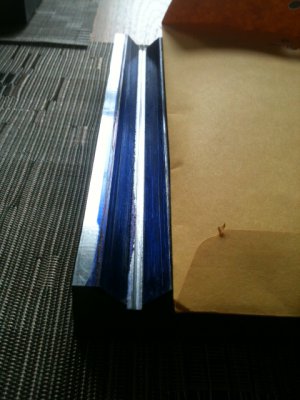
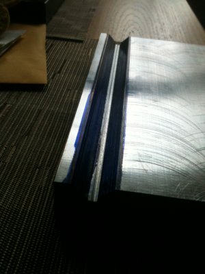
Here's a couple pics. It was freshly blued and run back forth on the lathe several times. No high spots, no rub areas. Just a smooth set of fine rub lines all the way across on both sides.... you can see exactly where the bluing is has made contact. Also the transfer onto the ways is very even. You might be able to see what looks one scratch on the right side of the groove. That is from the lip of the bluing applicator bottle. It rubs when you brush the other side. On the left side the contact area is the innermost 2/3 of the groove as, the corresponding way surface on that left side is "shorter" (i.e. less surface contact) than the other side which has full-profile contact. For some reason, they ground the ways that way.

Ray


Groove 8.JPGGroove 9.JPG

Groove 8.JPG Groove 9.JPG
 
Oh, one other thing... In addition to a HSS lathe bit, I used a 1/2" wide flat file that is smooth on the edges. It's only about 1/32" thick which is thin enough that when you lay it flat, you can use your thumbs to direct the force right on a high spot. First I would scrape it with the HSS then, I'd go over it lightly with the file just until it started to touch the blued area around it. That way, you're only taking off the high spot and smoothing it down w/o making low spots lower.

This didn't mess-up my hands as much as I though. I just had a round of cortisone shots in the the knuckles not long ago and didn't want to undo that. I iced my hands afterward which always helps. The hands are fine after all this -Wheew! -Can't seem to get the blue out of the skin though... :).


Ray
 
A tiny bit more progress here. Things are going slow because I had a little procedure on my foot today and can only stand for a short while.

-As promised, I installed a shim about 1/4" thick and it's bolted in from the top side. This allows me to bring the shim down slowly until it's hitting flat. I milled the channel for it and made the shim and it was about 5 thou oversized -which is exactly what I was shooting for. The original mill marks were several thou deep and this was the first test fit after SG'ing the mill marks off the shim. It is very, very close to making perfect contact. I'd say it has slightly less than a thou to come off before it's dead flat. The "guestimate" is very consistent with the measurement from reading the top of the plate with a DI installed on the crossfeed.

I'd like to finish it tonight but, the foot is not cooperating. It will be better tomorrow (the foot) and the plate will be finished too!

Ray

PS: Someone in a different post asked what kinds of projects are appropriate for a surface grinder. I sure hope that guy is reading this... I gotta tell you, it is very gratifying to dial in 0.0001" on the SG and the micrometer shows exactly that amount after the pass is made. No other tool can do that kind of work...

Shimmed.JPG

Shimmed.JPG
 
A teeny, tiny bit of progress tonight. Just made the keys for the sliding plates, milled from a drop piece of 4140 then surface ground 5 thou oversize of the slot. It will be heat treated and surface ground a final time for perfect fit.

I had a good wheel on the SG but since it was a small piece I used it anyhow. Normally, I save my good wheels for important stuff not junk work like keys. Also, soft metal (un heat treated) doesn't grind very well and is very picky about what wheel you use. I dialed this in for 0.382 and it's end-to-end 0.3820. Surface grinders... you got gotta love e'm.


Ray

Key.JPG

Key.JPG
 
We're getting warmer...

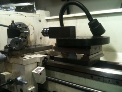
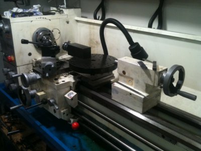
Here's a rough-out test fit. It's sitting on parallel blocks to see if the theoretical calculations agree with reality and make sure everything clears the U-shaped opening in the carriage. Yep, I guessed everything pretty close. Right now, the riser pieces are being rough cut but it takes a while. 1" steel plate isn't exactly butter. Once they're cut they'll be milled/ground to proper height and fastened. It's all going together with bolts -you'll see when I'm done... This will still have some up/down height adjustment. The sliding plates were aligned with two square keys instead of a V for the purpose of being able to put a shim between the plates if ever necessary. A V notch won't allow that as once you shim the plates, the V's won't come into contact.

After this, it's just a few more things: A) Push/pull screws for sideways adjustment B) Thread the main clamping bolt and make a nut C) Make and install a drive gear and handle to drive it off the rack gear D) Make the bottom clamp plate.

After that, I'll make some smaller attachment pieces. I started with big ones as those present the most clearance problems.

Roughout 1.JPGRoughout2.JPG

Ray

Roughout 1.JPG Roughout2.JPG
 
... Hope this isn't getting on your nerves but, here's more eye-candy and some words along the way...

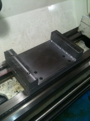
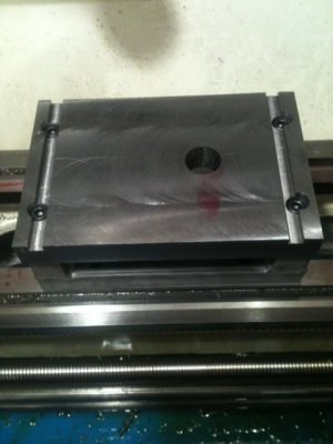
At the last minute, I decided to TIG the riser legs to the base plate. Noodled on that a bit wondering if the heat would warp all the hard work I put into that thing. Heck no... I had some tricks up my sleeve. I clamped several large pieces of aluminum as it sucks-up heat like a sponge. All the edges were beveled sharply about 1/8" so there was a nice v-groove to weld into. It was hit fast and hot. 120A, 1/16" tungsten with high arc force and 20% helium. That's effectively a 155 Amp weld. The bevels sucked up the rod so fast, I had a hard time keeping up with the filler. It was over so fast, the metal never knew what happened and it really didn't get all that hot. The welds were deep enough that I'll mill the outside weld caps off for better aesthetics.

Anyhow, the riser legs were cut intentionally a little high and you'll see why later. The bottom of the two top plates bolt on with four, 3/8" cap screws. It fits perfectly flat. I recheck the bed fit with bluing and there was no warping problem whatsoever.

Base.JPGBase 2.JPG

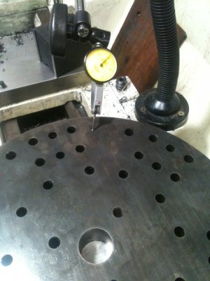
Preliminary checks with the DI are looking very good. From edge to center, it's about dead on. The parts are just set on there now and when things get bolted down, there might be runout but for now, it's in the ballpark for sure.

DI 1.JPGDI 2.JPGDI 3.JPG

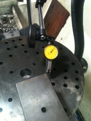
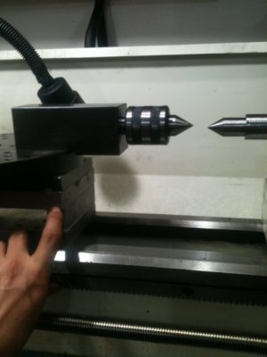
And here's why the riser legs were made tall. Right were my finger is pointed, the bottom of the two top-plates will be channeled out until I get the right height. Right now, I'm just lining-up with a TS point. If if screw-up and take too much off, disappointment but no worries as I could put shims on the riser legs before bolting the plate down. For now, I need to think of a good way to line-up to dead center. I'm sure I'll think of something but, I'm kinda brain-fried for the day. If you feel like tossing-out some ideas, I'm OK with that...

Line up.JPG

Oh, BTW, that was 1-1/8" plate. Had it in my head it was 1". This thing is really heavy and it's starting to feel really nice when you slide it on the ways.

Until tomorrow...

Ray

EDIT: And yes, I know... I'm not really holding the DI at an ideal angle but in this case, I'm not looking for a real reading, I'm looking for relative motion over the travel.

Base 2.JPG Base.JPG DI 1.JPG DI 2.JPG DI 3.JPG Line up.JPG
 
Will this turret index on each retraction or will you need to index it manually Ray?

"Billy G"
 
Are you kidding me? How much longer you want to see this thread go for? :LOL:

I got two other projects lined-up after this one...

-Seriously though, the thought of auto-index never entered my mind. I supposed there's plenty of space to rig something in there but, the plan was just to cut down on the number of times I'm switching stuff in/out of the tailstock. For starters, it would be nice to have a small drill chuck with a permanent center bit and one with a live center, another with a dead center etc... This one will index by loosening a top bolt, lifting an alignment pin, manual spin to the next station and put the alignment pin back in place. If you look at the holes in the plate, you'll see one hole thats off to the side of the others. That's for the alignment pin.

Ray


Will this turret index on each retraction or will you need to index it manually Ray?

"Billy G"
 
Back
Top