Need a little electromics help

GrayTech

Registered
Registered
Joined
Jan 18, 2018
Messages
190
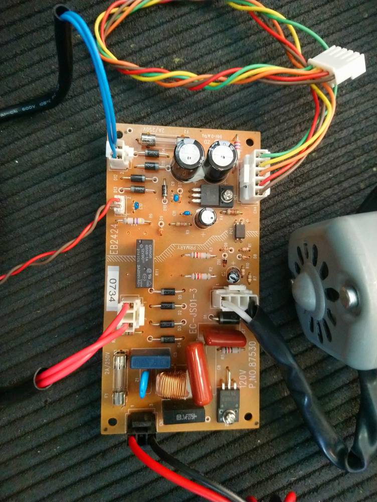
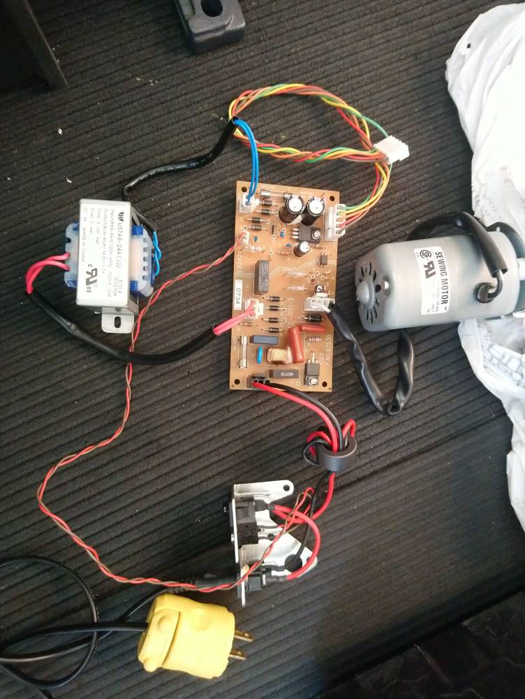
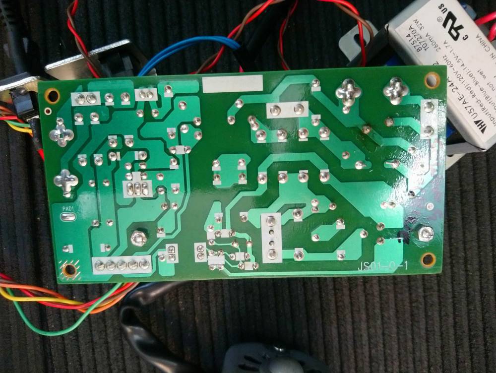
Im trying to build an x axis power feed for my X2 mini mill. I have a sewing machine motor and its controller board. The board has a 5 pin plug that connected to other electronics to select thread style etc. I need to figure out how to bridge this as it wont work just disconnected. Ive included images of both sides of the board. I know there are some electronics wizard members here, so I'm hoping someone can help out. Electronics is not my strongest suite. Thanks in advance.
2faf5c59fbe729509fa9580aa438afc4.jpg
787dd082d33d5d546ce5ee99a8f6be4b.jpg
8741679265071911a2c04647e4823cef.jpg
 
A little more detail might help......

Did anything on the 5-pins change the speed of the motor, the direction of rotation, or just on/off?

-brino
 
hhhhmmmmmmm.....

It looks like green and yellow wires send low-voltage DC power out that harness.

Can you read and post the device markings on IC1 (the three lead device closest to the 5-pin connector)?

-brino
 
Last edited:
IC1 is...
AUK
711
S7812PI

Not getting any motor movement when everything plugged in, AC power supplied and the 2 pins (CN6) for the foot pedal shorted
I will test everything with a meter again tomorrow to make sure all parts are functional. Was running before i stripped it all from the machine.
Thanks brino
 
As i understand the foot pedal (which i didnt get with the machine) is a potentiometer so i will use a potentiometer across those 2 pins at CN6.
I have exhausted google looking for wiring diagrams for that machine with no results so I'm trying to figure out the 5 pin. I dont want to just start bridging pins for fear of damaging the board.
 
AC power supplied and the 2 pins (CN6) for the foot pedal shorted
I dont want to just start bridging pins for fear of damaging the board.
???

The small block labeled PC1 appears to be an opto-isolator feeding the motor speed control circuit. It is hard to tell for certain because the white painted blocks obscure the traces on the PC board, but it looks like the opto-isolator is fed by the center (orange) wire on the 5 pin connector. Pretty hard to figure out what sort of signal should be going into there without knowing what that connector went to. Is it possible it went to another circuit board?

The SCR or Triac that controls the motor (next to the 120V label) is not mounted to a heatsink, so this board is for pretty intermittent duty, may not hold up well for your intended use.


I think the opto isolator is controlling the triac (might be a mosfet as I think the motor is getting DC) and the relay is used for reversing the motor as they are the only 2 components crossing the hi / low voltage sides.

I would be more helpful but my brain hurt a bit tring to figure out the location of components on the track side photo
;)

Stu
 
my brain hurt a bit tring to figure out the location of components on the track side photo

You aren't kidding!

The red wire from the connector looks like it controls the relay. The tan wire looks like it has no connection, but that white paint makes it impossible see for sure.

This may help, I mirrored the image of the bottom of the board and placed it next to the top. Maybe a fresh set of eyes can spot something else:


cbd.jpg
 
Back
Top