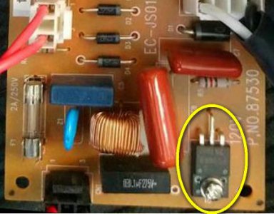
Need a little electromics help

one question i see is where is the red and brown wire going ? they look to be in the circuit that powers the relay , is their another switch they run to ?

I had convinced myself that the 2-pin connector with brown and red wires went off to an indicator lamp(LED?) mounted between the power cord and main power switch. @GrayTech can you confirm?

Also, what's the part number here:
ScreenShot088.jpg

-brino
 
I had convinced myself that the 2-pin connector with brown and red wires went off to an indicator lamp(LED?) mounted between the power cord and main power switch.

I think the 2 pin red and brown go to a jack that the foot control plugs into.
 
Thanks @RobertB, I still haven't see the "CN6" designator that was talked about above.....one issue with distance debug.....
-brino
 
The thin brown and red wires go to the foot pedal to control the motor speed.

Part number requested is
G
FS10KM
9A7302

Brown wire in 5 pin harness is isolated as per continuity test, its not connected to anything on the board.

Tested the motor with another driver I built for my bandsaw DC treadmill motor of same voltage and torque is not good at lower rpm. It will move the table fine but I dont think it will work well enough when cutting forces come into play. I'll use this 4000 rpm motor for another project and dig through my motor collection for something with more horsepower. I'd still like to get this board working though so not giving up just yet.

The part is a 10 amp mosfet

The universal motors are normally quite high rpm, I have one on a precision drill press that is high rpm where it works well. I think ur right about the low end torque without a big old reeducation geartbox.

Stu
 
Yeah, sewing machine motors are pretty anemic at lower rpm's. Even on a sewing machine where they have a pretty good reduction (about a 1/2" motor pulley and 4" to 5" machine pulley) at low rpm they often need a little hand assist just to poke a sharp needle through a couple of layers of fabric. Once you get that motor up above 5 or 6 hundred rpm they will zip right along.
 
Opinion only!!!!!! First job is to seperate the Electrical and the Electronics. The two are distinctly different areas of knowledge and not to be confused one with the other.

The motor is a generic sewing machine motor, series universal, with only two wires. What that indicates, to me, is that the motor is not reversable without an internal modification. The wires for the brush rigging and the stator must seperate at some point, leaving four (4) conductors to the outside. This applies whether it is run on AC or DC. The bottom line here is that the motor is not reversable as it is.

It can be connected either AC directly, or through a rectifier to get DC. Using AC, the speed is regulated with a reostat, like a pot but only two leads and heavier, stouter, and more expensive. I have a couple rigged to my Dremel and other electric drills where I can use my foot while my hands are busy. Or by using a triac to chop up the sine wave. Just like a light dimmer but rated for higher current.

Using DC, there are two (2) methods of control. The first using voltage control to control speed, with lower starting torque. The other using Pulse Width Modulation, to me the preferable of the two. PWM applies full line voltage (and current) in pulses, the width of the pulse controlling how much net power is applied.

Looking at your controller board at first glance, I am betting on a voltage controller. That's not to say for sure, just my first glance opinion. For use on a machine tool such as you indicated, my first instinct would be to find a different motor. A DC motor with a permanant magnet field would be best as it only uses two conductors. With a four wire motor, it would be preferable (highly) to reverse the armature, leaving the field the same polarity. This from the "old school" electric shop, not a hard and fast rule.

The main issue is that you do not need to use line (120) voltage equipment. An automotive window motor is reversable, albeit a bit large for your application. The important point is to have all external electrical equipment the same voltage so you can use a single power supply.

This doesn't answer your question directly, but with all the input you've been receiving it will give rise to some thought, if nothing else.

Bill Hudson​

.
 
Last edited:
An automotive window motor is reversable, albeit a bit large for your application. .

I used windshield wiper motors for mine. Both types have the advantage that they are geared motors with high torque and low rpm outputs. And both are very cheap, got my wiper motors for $10 each at a junkyard.
I went with the wiper motors because I knew they are designed for continuous duty. Don't know how a window motor would hold up. Their design use is only 3 to 4 seconds at a time.
 
Thanks for all the input guys. This forum is awesome because its members are aesome.
I forgot about wiper motots. They should be speed controllable like any other dc motor right?
I have some AC speed controllers snd rectifiers. If i use a transformer it should be connected between the controller and rectifier correct?
I have heard that this method of speed control is hard on electric motors and smoothing capacitors help some. Any insight on this?
 
I used windshield wiper motors for mine. Both types have the advantage that they are geared motors with high torque and low rpm outputs. And both are very cheap, got my wiper motors for $10 each at a junkyard.
I went with the wiper motors because I knew they are designed for continuous duty. Don't know how a window motor would hold up. Their design use is only 3 to 4 seconds at a time.

A wiper motor is not always reversable. It depends on a permanant magnet field as opposed to a wound field. A PM motor is reversable, a wound field motor is not, without all four leads coming out. The load on a machine tool is nowhere near as heavy as a window regulator. A window motor should run continuously fairly easily in that application.

Now, in response to the OP's second question; A transformer should never have DC applied to the input, so the rectifier should always be below the transformer. There are cases where a DC input is used, but those are considered rare. A X-former big enough for a motor drive will be expensive, I would recommend a switching power supply unless you are capable of winding your own x-former. I've done so several times but it is a PITA.

The speed control will come below the rectifier. Using a Pulse Width Modulation controller is highly recommended. It gives much more controllable speed control at lower speeds. Never apply an AC control, such as a light dimmer or router speed control, to the input of a transformer. It lets the smoke out of the transformer in short order. A PWM control isn't absolutely required, but is highly recommended. Mine come from M P Jones Assc, MPJA.com. Look for something heavy enough for two or three times the rated current, they are cheap enough. Motors are hungry when starting.

To reiterate, use a transformer from 120 to low voltage. Rectifier is next, the first item on the low voltage side. Then a capacitor, if one is used. This is the point to use a switching supply if that is prefered. Then a speed controller. The motor can be reversed electronicly but I would prefer a relay. It only requires a (continuous) pulse to pick up and a small snubber cap to clean it up. And lastly the motor.

A smoothing capacitor isn't really necessary on the input of a PWM controller, but does smooth things up a lot. Use a medium size, 500uF to 1000uF per amp. It still won't be battery smooth, but you won't notice the difference without an O-scope.

.
 
Back
Top