Need Assistance On Drum Switch Wiring

Dollar Bill

H-M Supporter - Gold Member
H-M Supporter Gold Member
Joined
Sep 3, 2018
Messages
14
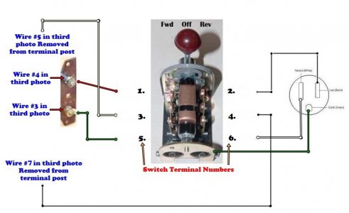
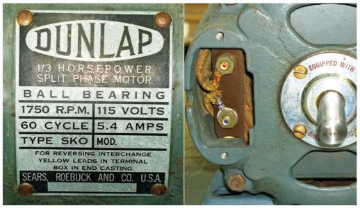
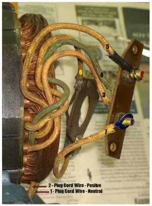
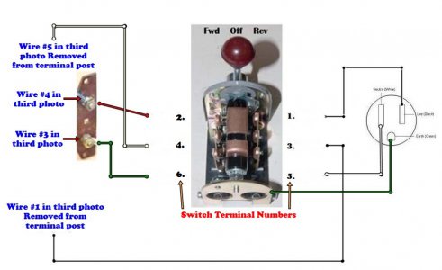
Over the last couple of weeks, I’ve read way too many posts about how to do this and it seems the more I read, the less I understand. The motor data plate and terminal box are shown in the first photo. The second photo shows the drum switch I’m using and the third photo shows the internal motor wiring. I’ve numbered them for ease of reference as most of them appear to be yellow except for the two green wires. The last photo shows how I wired in the drum switch and it spins in the right direction both ways but I’m unsure if it is running on the start windings. Also, I capped off and did not use wires 1 and 2 (3rd photo) which is where the cord was originally connected - Is that OK or is there a more correct way to wire in the reverse switch?

I truly appreciate any help you can offer as I’m quite ready to move onto the next phase in my lathe restoration.
1.jpg
2.jpg

NOTE: See Post #4 for correct diagram for the Furnas R-1 drum switch. The diagrams above are for the "other" type of switch.
3.jpg
4.jpg
 
Last edited by a moderator:
Over the last couple of weeks, I’ve read way too many posts about how to do this and it seems the more I read, the less I understand. The motor data plate and terminal box are shown in the first photo. The second photo shows the drum switch I’m using and the third photo shows the internal motor wiring. I’ve numbered them for ease of reference as most of them appear to be yellow except for the two green wires. The last photo shows how I wired in the drum switch and it spins in the right direction both ways but I’m unsure if it is running on the start windings. Also, I capped off and did not use wires 1 and 2 (3rd photo) which is where the cord was originally connected - Is that OK or is there a more correct way to wire in the reverse switch?

I truly appreciate any help you can offer as I’m quite ready to move onto the next phase in my lathe restoration.

View attachment 307198

Your picture is a bit hard to follow. You said you capped off #1 and did not use it yet you show it connected to terminal 3 on the drum switch and you do not show #7, is that mis-labeled?

Take a look at post #23 in this thread https://www.hobby-machinist.com/threads/wiring-help-needed.80487/ in your case the Red and Black would instead be your #'s 5 and 7
 
Bill,

If you have an ohmmeter, confirm that wire #1 is connected to or is the same wire as #4.

Confirm that 2 and 3 are connected together (not through a winding).

Confirm that 5 and 6 are connected through a winding (specifically the Start winding).

As RobertB pointed out, in your 4th photo, you say wire #1 goes to switch #3. Don't you mean wire #7?

Also, in your photo #4 you have the switch terminal numbers swapped left to right from how they are shown in the switch diagram in your photo # 2. That makes it not possible to say whether that is safe or not.
 
Gentlemen, I do apologize for the errors you pointed out. Having less than zero experience with A/C motors, I really got wrapped around the axle trying to figure this out myself and my confusion showed up in the graphics. Also, the schematics for the drum switch in my original post are incorrect too. At any rate, I've corrected the mistakes in the attached photos.

RobertB & wa5cab, I will follow both your recommendations and report back tomorrow. Thank both of for the kind assistance!!4.jpg

2.jpg
 
OK. Note that the Furnas R-1 (and other brands wired like it) is the better choice switch configuration for single phase Capacitor Start and Split Phase AC motors. If you run the AC line cord to the switch and only run the ground and four motor control wires from switch to motor, when the switch is OFF, there is no AC in the motor.

Anyway, that looks correct to me. Numbered wires used externally are 3, 4, 5 and 7. FWIW, 4 is connected to 1 and 3 is connected to 2 internally. So 1 and 2 must be capped (insulated).
 
Also, the schematics for the drum switch in my original post are incorrect too.
Do not refer to the post I directed you to, that would only apply to the switch you showed you had at first, not the one you actually have!

Anyway, that looks correct to me. Numbered wires used externally are 3, 4, 5 and 7. FWIW, 4 is connected to 1 and 3 is connected to 2 internally. So 1 and 2 must be capped (insulated).
^^^This^^^
 
RobertB: Sounds like you have it wired correctly from your description if it starts and runs in both directions- your motor is called a "split-phase" type with no starting capacitor, hence the starting torque will be less than a capacitor-start type, but that may not be a problem for your application.
Mark
 
"If you have an ohmmeter, confirm that wire #1 is connected to or is the same wire as #4.
Confirm that 2 and 3 are connected together (not through a winding).

Confirm that 5 and 6 are connected through a winding (specifically the Start winding)."

wa5cab
, As promised, I wanted to follow up with your original reply.... I did confirm wires both 1&4 and 2&3 Ohmed at .6 Ω with my 40 year old Radio Shack digital multimeter and wires 5&6 read 4.5 Ω which makes me think 5&6 are the starting coil as you indicated. Just for comparison, where would I take a reading for the run coil? Just to ease my mind that during my op test last week it wasn't running on the start coil. My research over the past couple of weeks indicates the run windings will have greater resistance than the start winding?
 
RobertB: Sounds like you have it wired correctly from your description if it starts and runs in both directions- your motor is called a "split-phase" type with no starting capacitor, hence the starting torque will be less than a capacitor-start type, but that may not be a problem for your application.
Mark
Hi Mark, thanks for the reply. The motor seems to power my 12x24 Craftsman lathe OK. I just got the lathe this summer and was not able to speak with the original owner. Motor has likely been on the lathe since it was new. It has a build date of 11/48. I haven't torn into the headstock to check the date on the spindle bearings - That's my next move, hopefully next week.
 
"If you have an ohmmeter, confirm that wire #1 is connected to or is the same wire as #4.
Confirm that 2 and 3 are connected together (not through a winding).
Confirm that 5 and 6 are connected through a winding (specifically the Start winding)."

wa5cab
, As promised, I wanted to follow up with your original reply.... I did confirm wires both 1&4 and 2&3 Ohmed at .6 Ω with my 40 year old Radio Shack digital multimeter and wires 5&6 read 4.5 Ω which makes me think 5&6 are the starting coil as you indicated. Just for comparison, where would I take a reading for the run coil? Just to ease my mind that during my op test last week it wasn't running on the start coil. My research over the past couple of weeks indicates the run windings will have greater resistance than the start winding?

Regardless of relative resistance, 5&6 or 5&7 are clearly the start winding or start circuit as 6 and 7 are connected to the centrifugal switch. The Run winding is connected between 1 and 2, and between 4 and 3, whichever is the easiest to get to.

The Start winding may have fewer turns than the Run winding, which lowers the resistance. However, it may also use smaller gauge wire, which raises the resistance. So it isn't in general safe to ID Start and Run windings solely by resistance. However, in this case, Wire 6 is obviously connected to the start switch so it must go to the start winding. Therefore, the other winding has to be the Run winding.
 
Back
Top