Need help on grounding a milling machine

Chris Brainard

Registered
Registered
Joined
Jan 22, 2018
Messages
4
I'm new to this forum. My professional background is in weIding/steel fabrication (45 years) and my hobbies are woodworking and building and flying model airplanes (50 years). I bought a Hartford 9" x 42" milling machine (Bridgeport clone) several years ago (for the bargain basement price of $200.00) with the intent of building an aluminum adapter that would mount to the spindle. A woodworking router would be mounted to the adapter and I would clamp my wood to the table and then use the "X" and "Y" axis of the table and the down feed of the spindle to do deep (and accurate) mortising. The machine shop I got it from disassembled it so I could get it home in a couple of trips. It sat in my shop for six years until I finally got around to reassembling it. It had been used in a fiberglass shop and was covered with some sort of black tar like substance. It took longer to clean that off then it did to reassemble it. Now, that it is reassembled, backlash adjusted and broken parts replaced, I'd like to get it running so that I can use it to make small parts for the model airplanes that I fly. I bought a VFD so that I can convert 240 volt single phase to three phase and am in the process of learning how to wire and program it. This may sound silly, but I don't know how this machine is to be electrically grounded. Would someone be kind enough to give me some guidance?
 
Hi Chris,
motors are grounded by attaching the ground wire to the motor case.
most motors will have provision inside the motors electrical enclosure to attach the (green, or green/yellow, or uncoated) ground wire by means of a screw that threads into the motor housing.
the VFD should also have a spot for ground as well, sometimes located on the heastsink of the VFD, sometimes on the terminal strip internal to the VFD
 
I recently set up my first VFD. 3 wires from the plug/panel to the VFD. 2 hots (black/red usually) 1 ground (green or bare usually). Neutral is not needed for my setup. Yours might need one, that's white.

Then you need 4 wires from VFD to the machine. 3 hots, L1/L2/L3. I think there are some color codes, but I don't know them. I made my own wiring. The last is ground. Connect the ground to the motor case, the connection housing often has a lug in there you can use. You can also ground the machine chassis, but the motor is usually hard mounted to the machine and will ground that way. You can verify with an ohm meter to be sure.

As for wire size, check the motor nameplate or the VFD documentation for the maximum current (amps). There are charts for the electrical code that tell you which sizes to use.

If the motor spins the wrong way, swap any two wires. L1/L2/L3, not ground of course. :)

If you fly brushless electric, the motors are similar, just bigger. The ESC is a VFD.
 
What you want is for any electricly operated part of the machine to be attached to a grounding lug on the power plug. Or to the source, if it is hardwired.... The motor and the VFD are included in this statement. Since you probably are using housepower (120/240 V 1 Ph) the power plug may be as large as a range plug. Most any plug bought these days will have a clearly marked grounding pin, usually by painting green.

The line cord will have (usually) Black, Red(or Blue), White, and Green. The White wire in this case will not be used. However, it may be the only grounded lead for the cord-set and necessarily the only practical way to get a good ground. There is no need for a single lead. Only that a metal part of each piece be connected to the Green pin. Wire size should be the same, or one size larger, as the power cord.
 
Last edited:
Hi @Chris Brainard ,

I have nothing to add in answer to your question.

I just stopped by to say Welcome to the Hobby-Machinist!

You've come to the right place. You will find many people here with very similar interests, and also with totally different perspectives.
That's what keeps me coming back. The one constant is respect for everyone.

It sounds like you'll have a lot on knowledge to share on welding.

-brino
 
Hi Chris, Welcome abord,
I have set up several VFDs, I ground everything to the ground on the terminal bar of the VFD, the ground on the line in, the ground from the motor and if used, the shield grounds from the control cables (these should only be grounded at one end to prevent ground loops).
What brand and model VFD do you have? All some pictures of the mill and VFD are always welcome!
 
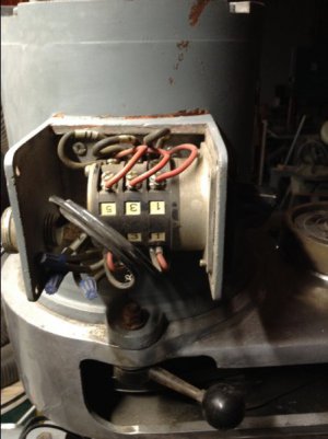
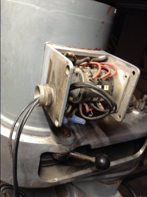
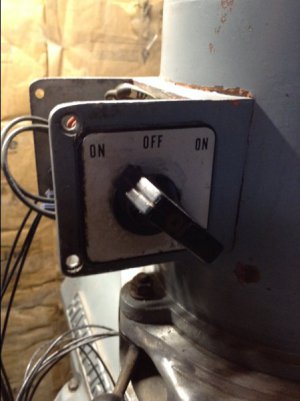
I've got the Isacon HY Series VFD 2.2 kW. When my milling machine was taken out of service, they simply cut the power wires (3) coming into the switch (forward-off-reverse), which is mounted directly on the motor. There is no ground wire coming out of the switch, hence my question on grounding. It didn't make sense to me that they would cut the power wires and then go inside the motor or switch to unscrew the ground cable. I have a whole shop full of woodworking tools which run on 120 or 240, but it's all single phase. This is my first venture into three phase. I thought maybe the whole machine had to be grounded. Looking at the switch more closely, it has a threaded fitting on the outside. Is it possible that this may have had a flexible steel cable that provided the ground? If so, that would explain why no grounding wire is coming out of the motor.
 
the switches themselves do not need to be grounded.
the machine ground may be very close to the incoming power cable upon entering the machine's electrical enclosure
generally, grounds are not made by flexible conduit. maybe the machine ground was made by other means
 
Give it good advice, allow to succeed or fail on its own sometimes, and set a good example. It should be well grounded.
 
This what I have. The switch is attached to a bracket mounted directly on the motor. There is a threaded steel conduit (?) fitting on the housing/bracket that the switch is mounted to. Would it make sense to ground off of that?

image.jpeg

image.jpeg

image.jpeg
 
Back
Top